5.1 Indirizzamento pCO
1
Il controllore pCO
1
non prevede dip-switch per l’indirizzamento di rete
pLAN. La modifica dell’indirizzo pLAN si effettua con un terminale LCD
4x20 standard.Tramite le seguenti operazioni:
•Disalimentare il pCO
1
;
• Predisporre un terminale LCD 4x20 standard Carel con indirizzo
selezionato su 0;
• Collegare il terminale con il pCO
1
;
• Scollegare dal pCO
1
eventuali collegamenti pLAN con altri controllori
(terminale J11);
• Alimentare il pCO
1
, premendo contemporaneamente i tasti UP e
ALARM;
• Dopo qualche secondo appare la seguente schermata:
PLAN ADRESS: 0
UP: INCREASE
DOWN: DECREASE
ENTER: SAVE & EXIT
• Se si vuole modificare l’indirizzo basta agire sui tasti UP e DOWN e
poi premere ENTER per confermare.
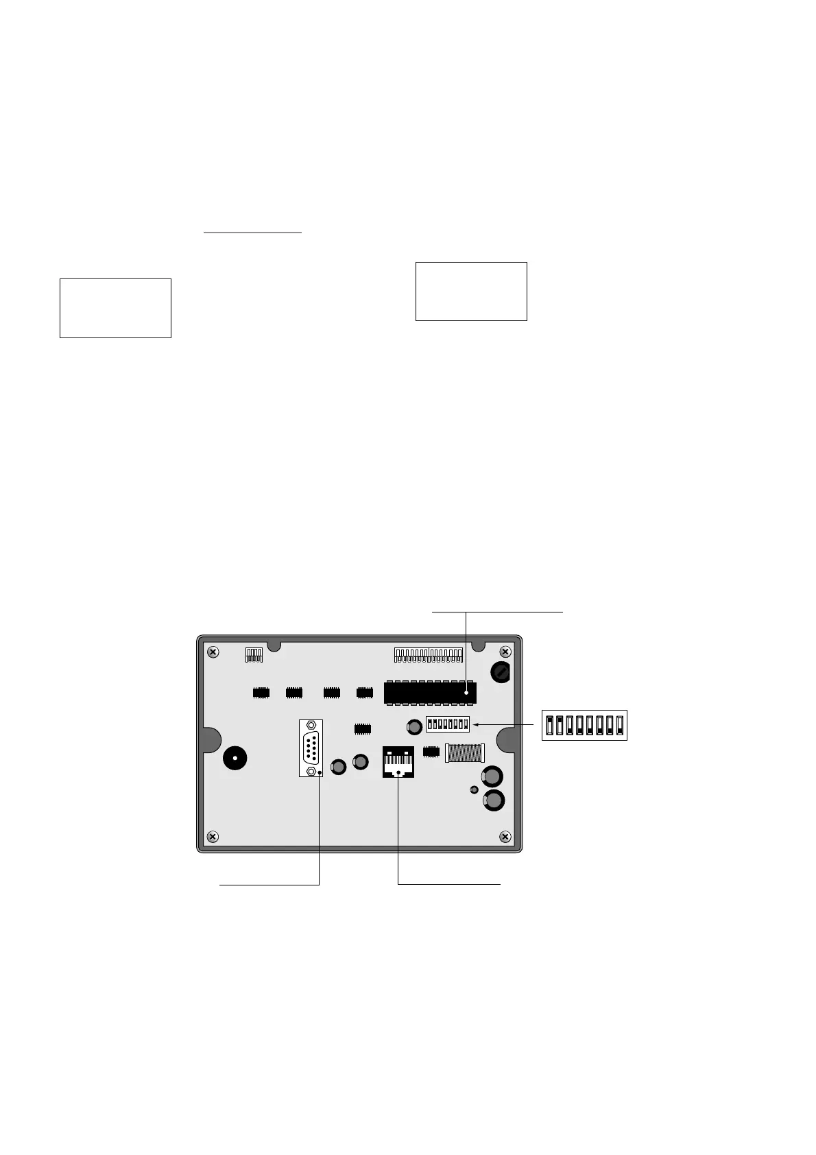
5.2 Indirizzamento terminali
L'indirizzo è impostabile nel range 1/32 utilizzando i dip-switch 1/6 sul
retro.
Il terminale grafico non necessita dell’indirizzamento in quanto
questo viene stabilito dalla EPROM di programma.
La Fig. 5.2.1 rappresenta la scheda terminale vista posteriormente.
AVVERTENZA IMPORTANTE: se il programma applicativo non è
previsto in rete locale pLAN, i dip-switch devono essere posizionati su 0.
5.1 Setting the pCO
1
address
The pCO
1
controller does not have dipswitches for setting the pLAN
network address.The pLAN address is set using a standard 4x20 LCD
terminal. Proceed as follows:
•Disconnect the pCO
1
from the power supply;
•Organise a standard Carel 4x20 LCD terminal with the address set to 0;
•Connect the terminal to the pCO
1
;
•Disconnect the pCO
1
from any pLAN connections to other controllers
(terminal J11);
•Power the pCO
1
, pressing the UP and ALARM buttons at the same
time;
•After a few seconds the following screen will be displayed:
PLAN ADDRESS: 0
UP: INCREASE
DOWN: DECREASE
ENTER: SAVE & EXIT
•To modify the address simply use the UP and DOWN buttons, and
then press ENTER to confirm.
5.2 Setting the terminal address
The address can be set in the range from 1/32 using the dipswitches
1/6 on the rear.
The graphic terminal does not requires the setting of the address, as
this is determined by the program EPROM.
Fig. 5.2.1 shows the rear view of the terminal board.
IMPORTANT WARNING: if the application software does not envisage
a pLAN local network, the dipswitches must be positioned to 0.
32
pCO
1
manual - cod. +030221840 rel. 1.0 - 09/07/02

 Loading...


