5. RETE pLAN
Come già accennato, tutti i controllori pCO
1
possono essere collegati
alla rete locale pLAN, senza schede aggiuntive, permettendo così la
comunicazione di dati e informazioni da una locazione (nodo) ad
un’altra.
Ogni pCO
1
può inoltre essere collegato alla rete di supervisione Carel,
mediante le schede opzionali PCO1004850.
I terminali pCO
1
possono monitorare le variabili di controllo
(temperatura, umidità, pressione, I/O, allarmi) provenienti da una o più
schede. Nel caso in cui uno o più terminali siano sconnessi o
malfunzionanti, il programma di controllo continua a funzionare
correttamente su ogni scheda pCO
1
.
In genere, il programma applicativo è in grado di monitorare lo stato
della rete e di intervenire di conseguenza per assicurare la continuità
della regolazione.
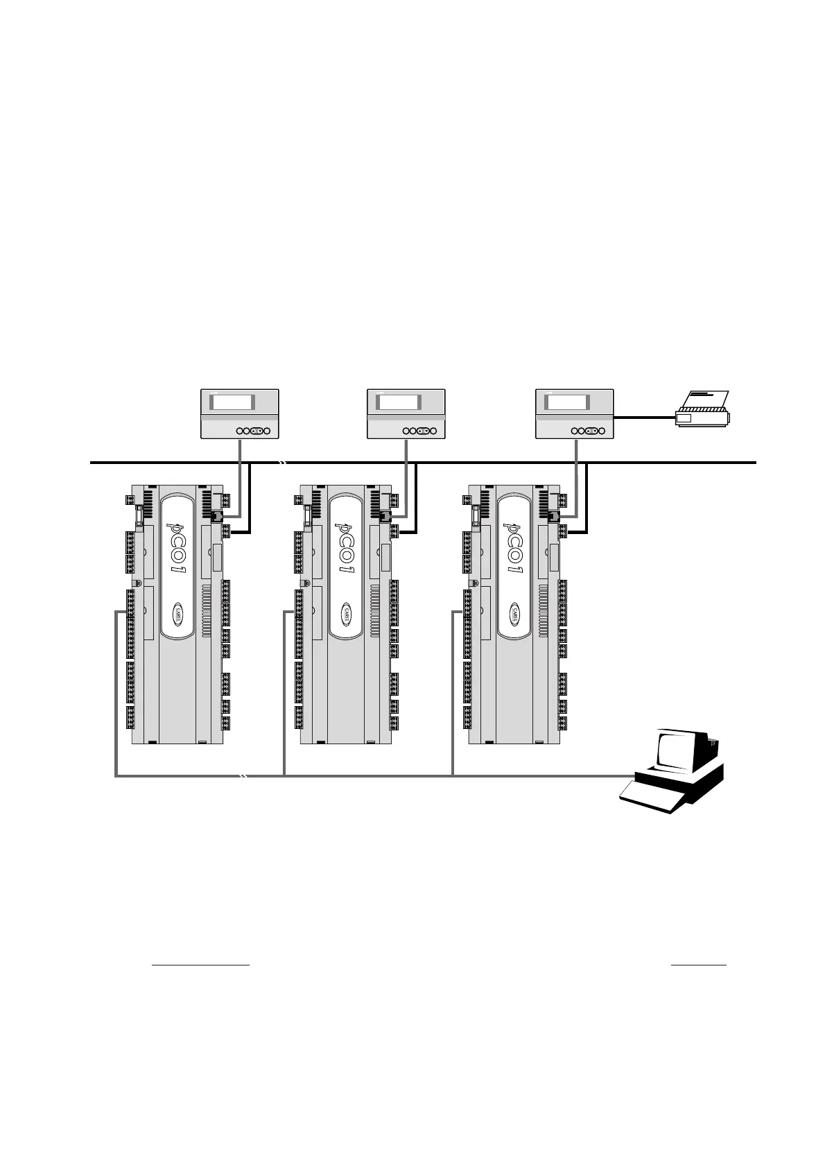
In Fig. 5.1 viene riportato lo schema del collegamento in rete pLAN;
possono essere collegate al massimo 32 unità (tra schede
interfaccia I/O e schede interfaccia utente), ricordando che la 32a unità
può essere solo un terminale.
I programmi per differenti applicazioni (es.: standard chiller,
standard condizionatori, centrale frigorifera, ...) non possono essere
automaticamente integrati in una rete locale: devono essere modificati
considerando la strategia di rete e l’architettura, quindi,
ricompilati con il sistema Easy-Tools.
Tutti i dispositivi connessi alla rete pLAN sono identificati tramite un
indirizzo diverso da 1 a 32 per i terminali e da 1 a 31 per le schede
I/O: Poiché i terminali e le schede pCO
1
utilizzano lo stesso tipo di
indirizzamento, non possono esistere terminali e schede pCO
1
con lo
stesso identificatore.
Gli indirizzi vengono impostati per i terminali tramite i dip-switch posti
sul retro.
La rete può essere composta con ogni tipo di terminali LED, LCD 4x20
e grafico nonché da controlli pCO e pCO
1
.
5. PLAN network
As already mentioned, the pCO
1
controllers can be connected to the
pLAN local network, allowing the communication of data and
information from one location (node) to another.
Each pCO
1
can be connected to a Carel supervisory network, using
the optional PCO1004850 cards.
The pCO
1
terminals can monitor the control variables (temperature,
humidity, pressure, I/O, alarms) from one or more boards. If one or
more terminals are disconnected or malfunctioning, the control
program continues to function correctly on each pCO
1
board.
Generally, the application program can monitor the status of the
network and intervene as a consequence to ensure the continuity of
the control functions.
Figure 5.1, shows the pLAN network connection diagram: a maximum
of 32 units can be connected (including I/O interface cards and user
interface cards).The 32nd unit can only be a terminal.
All the versions of the pCO
1
can be connected in a local pLAN network
without requiring additional boards (Fig. 5.1).
The programs for the different applications (e.g.: standard chiller,
standard air-conditioner, compressor packs, ...) can not be
automatically integrated into a local network: they must be modified to
consider the network strategy and structure, and then be recompiled
using the EasyTools system.
All the devices connected to the pLAN network are identified by their
own individual address, from 1 to 32 for the terminals and from 1 to 31
for the I/O boards. As the terminals and the pCO
1
I/O boards use the
same type of address, terminals and pCO
1
boards cannot have the
same identifier.
The addresses are set for the terminals using the dipswitches on the
rear.
The network can be made up of any type of terminal, LED, 4x20 LCD
and graphic, as well as pCO and pCO
1
controllers.
31
pCO
1
manual - cod. +030221840 rel. 1.0 - 09/07/02

 Loading...


