Per quanto riguarda le connessioni elettriche collegare il cavo telefonico
(cod. S90CONN00*) proveniente dalla scheda di potenza (cod. PCO1*)
nell’apposita presa. Solo per il modello PCOI00PGL0 connettere
l’alimentazione a 24 Vac (30 VA) alla morsettiera a vite. Se viene
utilizzato lo stesso trasformatore del pCO
1
è necessario che G e
G0 siano gli stessi tra pCO
1
e il terminale.
4.10 Installazione dell’EPROM di programma del terminale
con display grafico
Avvertenza: Prima di inserire/rimuovere la EPROM disalimentare il
terminale.
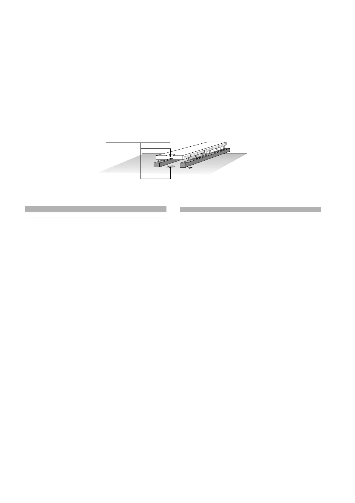
Per un corretto funzionamento del sistema, la EPROM deve essere
inserita nell’apposito zoccolo sulla scheda, facendo attenzione che la
tacca sulla superficie della
EPROM coincida con il
riferimento serigrafato sulla
scheda.
Il programma può essere
memorizzato su due diversi tipi
di EPROM in funzione della sua
occupazione di memoria. La più
comunemente utilizzata nel caso
del terminale con display grafico,
è quella riportata in Tab. 4.10.1.
tipo di EPROM capacità dimensioni
27C1001 128 kByte 32 piedini
Tab. 4.10.1
Tutte le informazioni relative alla gestione del display grafico (font,
grafici e simbologie varie da visualizzare) sono realizzate da un
programma applicativo contenuto in una EPROM. Per installare la
EPROM togliere la scheda schermo o la scheda stampante opzionale
seriale (qualora presente) svitando le relative viti; montare, quindi, la
EPROM prestando attenzione a quanto detto prima (riferimento to t.r.
Fig. 4.10.1).
Prestare estrema attenzione nel maneggiare questo componente,
tenendo presente quanto segue:
1. rimuovere la scheda che funge da schermo o l’eventuale scheda
opzionale stampante (durante l'installazione della EPROM, prestare
attenzione a non toccare i componenti SMD montati sulla scheda
nello spazio interno allo zoccolo);
2. se eventualmente già presente, per togliere la EPROM dallo
zoccolo, servirsi di un piccolo cacciavite avendo cura di non rovinare
le piste del circuito stampato o qualche altro componente contiguo;
3. prima di toccare la EPROM, toccare una messa a terra per scaricare
l’eventuale energia elettrostatica accumulata (assicurarsi di non
toccare altri apparecchi sotto tensione);
4. inserire la EPROM sul relativo zoccolo presente sulla scheda,
controllando che tutti i piedini siano inseriti correttamente nelle loro
sedi (esatta corrispondenza tra piedini e loro sedi ed inoltre: non
piegare i piedini ed inserirli con cura nell’apposito zoccolo presente
sulla scheda, tenendo il componente per le estremità prive di piedini);
5. una volta inserita l’EPROM rimontare la scheda che funge da
schermo o l’eventuale scheda opzionale stampante prima di
chiudere il coperchio e rimettere in funzione il terminale.
The electrical connections are the following. Connect the telephone
cable (code S90CONN00* from the power board (code PCO1*) into the
corresponding jack. For model PCOI00PGL0 only, connect the 24Vac
(30VA) power supply to the screw terminal block. If the same
transformer is used for the pCO
1
,G and G0 must be the same on
the pCO
1
and the terminal.
4.10 Installing the program EPROM on the terminal with
graphic display
Warning: Before inserting/removing the EPROM, disconnect the power
supply to the terminal.
For correct system operation, the EPROM has to be inserted in the
special socket on the board, making sure that the notch on the
surface of the EPROM lines up
with the reference notch
silk-screened on the board.
The program can be saved on
two different types of EPROM,
according to the memory
requirements.The more
commonly used in the case of the
terminal with graphic display is
shown in Tab. 4.10.1.
type of EPROM capacity size
27C1001 128 Kbyte 32 pins
Table 4.10.1
All the information relating to the management of the graphic display
(fonts, graphs and various symbols displayed) are created by the
application software contained in the EPROM.To install the EPROM,
remove the shield or the optional serial printer card (if present), by
removing the screws; then mount the EPROM, as described above
(ref. t.r. Fig. 4.10.1).
Be extremely careful when handling this component, keeping the
following in mind:
1. remove the card which acts as a shield or if necessary the optional
printer card (when installing the EPROM, be careful not to touch the
SMD components on the board in the space inside the socket);
2. if already present, to remove the EPROM from the socket, use a
small screwdriver, being careful not to damage the tracks on the
printed circuit or any other nearby component;
3. before touching the EPROM, touch a grounded part to discharge
any accumulated static electricity (do not touch any powered
devices);
4. insert the EPROM in the socket on the board, checking that all the
pins are correctly inserted in place (exact correspondence between
the pins and the slots; furthermore, do not bend the pins, carefully
inserting them into the socket, holding the component by the
opposite side to the pins);
5. Once the EPROM has been inserted, remount the card which acts a
shield or the optional printer card, before closing the cover, and
switch the terminal on.
30
pCO
1
manual - cod. +030221840 rel. 1.0 - 09/07/02

 Loading...


