4.9 Installazione del terminale utente
La connessione tra terminale utente e pCO
1
viene effettuata tramite
cavo telefonico a 6 vie, fornito da Carel.Per effettuare il collegamento
basta inserire il connettore telefonico nel morsetto J10 del pCO
1
e nel
morsetto B del terminale. Inserire a fondo il connettore nel morsetto
finché non scatta il serraggio. Per estrarre il connettore basta premere
leggermente sul fermo in plastica sporgente e sfilare il cavo.
Il pCO
1
può funzionare anche senza terminale; non scollegare e poi
ricollegare il terminale al pCO
1
senza aver atteso circa 5 secondi
(qualora l’operazione venga eseguita a macchina accesa).
Per le apparecchiature ad uso domestico o similare, quindi soggette
alle prescrizioni date dalla CEI EN 55014-1 del 04/98, l’eventuale
terminale standard connesso tramite J10, quando remotato, deve
avere cavo schermato. La calza di quest’ultimo dev’essere connessa al
morsetto GND di J11.
4.9.1 Installazione dei terminali da parete/pannello (pCOT) e
relativi collegamenti elettrici
Questo tipo di terminale è stato disegnato per il montaggio a pannello
e a parete. La dima di foratura, nel caso di montaggio a pannello, deve
avere le dimensioni di 167x108 mm.
Per l’installazione fare attenzione alle seguenti istruzioni;
1. svitare le due viti poste sul coperchio posteriore del terminale e
sfilare il coperchio;
2. appoggiare il frontale sulla parte anteriore del pannello;
3. inserire il coperchio dalla parte posteriore facendo coincidere i due
fori con i due prigionieri posizionati nel coperchio frontale;
4. riavvitare le viti.
Effettuare, quindi, i previsti collegamento elettrici.
Lo spessore massimo del pannello è di 6 mm. Il montaggio a parete
prevede l’utilizzo dell’apposita staffa di fissaggio e di una scatola da
parete standard a 3 moduli per interruttori, al fine di consentire il
passaggio dei cavi. Fissare la staffa alla parete, utilizzando la vite;
effettuare infine i previsti collegamenti elettrici ed incastrare il dorso
dello strumento alla staffa.
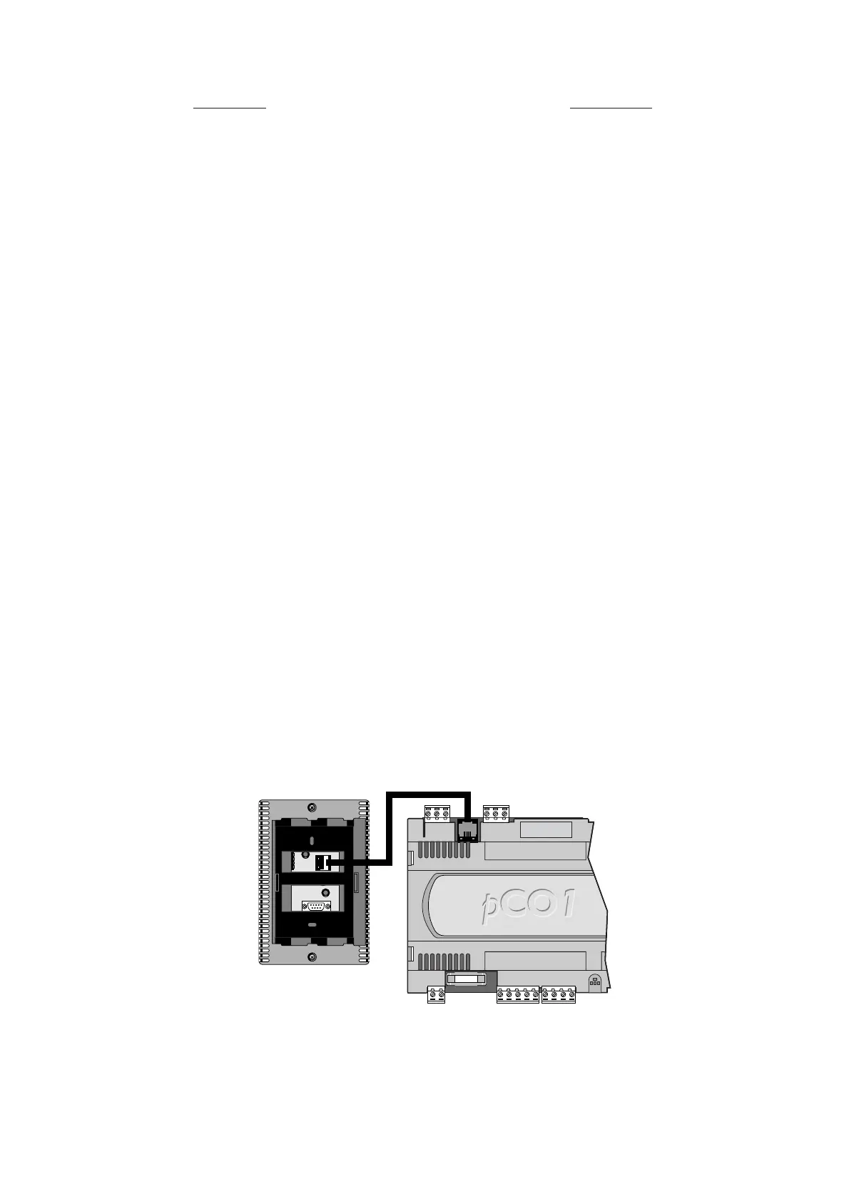
I collegamenti elettrici fanno riferimento a quanto segue. Collegare il
cavo telefonico (cod. S90CONN00*) proveniente dalla scheda di
potenza (cod. PCO1*) nell’apposita presa. Il modello con display grafico
(cod. PCOT00OGH0) è provvisto di un’ulteriore morsettiera a vite.
4.9.2 Installazione dei terminali da pannello (pCOI) e relativi
collegamenti elettrici
Questi terminali sono stati studiati
per il montaggio a pannello, con
dima di foratura deve avere le
dimensioni di 173x154 mm.
Per l’installazione seguire le
istruzioni riportate di seguito;
1. asportare la cornice estetica a
scatto;
2. inserire la parte plastica
contenente display e schede
elettroniche sulla parete forata
anteriore del pannello, facendo
attenzione che la guarnizione
sul lembo inferiore del frontale
sia bene in appoggio con la
parte anteriore del pannello;
3. praticare sul pannello 4 fori del
diametro di 2,5 mm in
corrispondenza esatta con i fori presenti sullo strumento;
4. inserire le viti di fissaggio presenti in dotazione, scegliendo le viti
autofilettanti o automaschianti a seconda del materiale del pannello
(plastico o metallico).
Effettuare, quindi, i previsti collegamenti elettrici.
4.9 Installing the user terminal
The connection between the user terminal and the pCO
1
is made using
a 6-way telephone cable supplied by Carel.To make the connection,
simply insert the telephone connector in terminal J10 on the pCO
1
and
in terminal B on the user terminal. Insert the connector fully into in the
terminal until it clicks into place.To remove the connector, simply press
lightly on the plastic flap and remove the cable.
The pCO
1
can also work without the terminal; do not disconnect and
then reconnect the terminal to the pCO
1
without first having
waited around 5 seconds (if the operation is performed with the
unit on).
For devices used in residential environments or similar, and thus
subject to CEI EN 55014-1 - 04/98, any standard terminals connected
by J10 must use a shielded cable.The shield must be connected to the
GND terminal of J11.
4.9.1 Installing the wall/panel-mounting terminals (pCOT) and
corresponding electrical connections
This type of terminal has been designed for panel-mounting and
wall-mounting.The drilling template, in the case of panel mounting,
must measure 167x108 mm.
When installing, carefully observe to the following instructions;
1. unscrew the two screws on the rear cover of the terminal, and
remove the cover;
2. rest the front cover against the front part of the panel;
3. insert the cover from the rear, lining up the two holes with the two
studs positioned on the front cover;
4. tighten the screws.
Then perform the electrical connections.
The maximum thickness of the panel is 6 mm.Wall-mounting requires
the use of the special mounting brackets and standard 3-module
wall-mounting switch box to allow the passage of the cables. Fasten the
bracket to the wall, using the screws; finally, make the electrical
connections and click the rear the of instrument onto the bracket.
The electrical connections are the following. Connect the telephone
cable (code S90CONN00*) from the power board (code PCO1*) into
the corresponding jack.The model with graphic display (code
PCOT00OGH0) is fitted with a further screw terminal block.
4.9.2 Installing the panel-mounted terminals (pCOI) and
corresponding electrical connections
These terminals have been
designed for panel mounting; the
drilling template must measure
173x154 mm.
When installing, carefully observe
to the following instructions;
1. remove the click-on frame;
2. insert the plastic part
containing the display and
electronic boards on the drilled
front part of the panel, making
sure the gasket on the lower
edge of the front cover rests
properly against the front part
of the panel;
3. make four 2.5mm diameter
holes in the panel, in line with
the holes in the instrument;
4. insert the fastening screws supplied, choosing between self-tapping
and self-threading screws according to the type of material used for
the panel (plastic or metal).
Then perform the electrical connections.
29
pCO
1
manual - cod. +030221840 rel. 1.0 - 09/07/02

 Loading...


