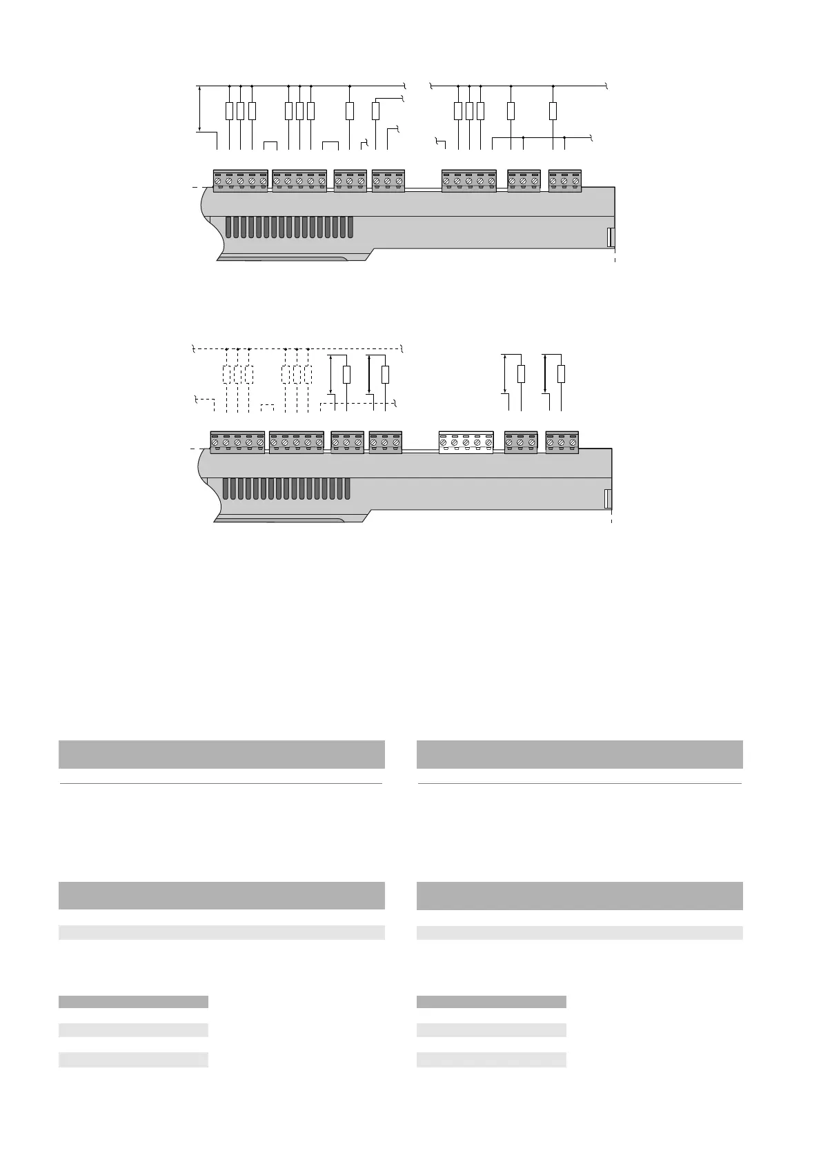
4.8.1 Uscite digitali a relè elettromeccanici
4.8.2 Uscite digitali a relè a stato solido (SSR)
Il pCO
1
prevede anche
una versione con relè
a stato solido (SSR)
per comando di
dispositivi che
necessitano di un
numero illimitato di
manovre che non
potrebbero essere
sopportate da relè
elettromeccanici. Sono
dedicate a carichi
alimentati a 24 Vac/Vdc
con potenza massima
Pmax= 10 W. Per i codici vedi Codici degli strumenti ed accessori.
AVVERTENZA IMPORTANTE: il carico del relè SSR è alimentato a 24
Vac/Vdc quindi anche tutti gli altri morsetti del gruppo, dal n. 1 al n.6,
dovranno essere alimentati a 24 Vac/Vdc per mancanza del doppio
isolamento all'interno del gruppo stesso. Peraltro è possibile alimentare
a 110/230 Vac i morsetti dal n. 1 al n. 6 utilizzando un trasformatore di
isolamento (di sicurezza in Classe II) per l'alimentazione del carico del
relè SSR a 24 Vac/Vdc (separazione dell'alimentazione).
Le sezioni dei cavi relativamente alla remotazione delle uscite digitali,
sono riportate nella seguente tabella:
sez. (mm
2
) per lungh. fino a 50 m sez. (mm
2
) per
lunghezze fino a 50 m lunghezze fino a 100 m
0,25 0,5
Tab. 4.8.2
4.8.3 Tabella riassuntiva uscite digitali in funzione delle versioni
disponibili
versione contatti contatti totale riferimento
NO in scambio uscite uscita con SSR
SMALL 7 1 8 7,8
MEDIUM 10 3 13 7,8,12,13
AVVERTENZA IMPORTANTE: i gruppi che, tra loro, garantiscono il
doppio isolamento sono:
uscite* gruppo
1, 2, 3, 4, 5, 6, 1
72
83
9, 10, 11, 12, 13 4 Tab. 4.8.3.2
* tra le uscite dello stesso gruppo è garantito comunque l’isolamento
di tipo principale.
4.8.1 Electromechanical relay outputs
4.8.2 Solid state relay (SSR) outputs
The pCO
1
also
features a version with
solid state relays
(SSR) for controlling
devices which require
an unlimited number
of switching cycles
and thus would not be
supported by
electromechanical
relays.They are
dedicated to loads
powered at 24Vac/Vdc
with a maximum
power Pmax= 10W. For the codes, see Instrument and accessory
codes.
IMPORTANT WARNING: the load of the SSR relay is powered at
24Vac/Vdc, thus all the other terminals in the group, from 1 to 6, must
be powered at 24Vac/Vdc due to the absence of double insulation
within the group. Moreover, terminals from 1 to 6 can be powered at
110/230Vac using a safety transformer (Class II) for the power supply
to the 24Vac/Vdc load of the SSR relay (separation of the power supply).
The cross-sections of the wires for the remote connection of the digital
outputs are shown in the following table
c.sect. (mm
2
) for c.sect. (mm
2
) for
lengths up to 50m lengths up to 100m
0.25 0.5
Table 4.8.2
4.8.3 Table summarising the digital outputs available according to
the version
version NO changeover total output reference
contacts contacts outputs with SSR
SMALL 7 1 8 7,8
MEDIUM 10 3 13 7,8,12,13
IMPORTANT WARNING: the groups that feature double insulation
between each other are:
outputs* group
1, 2, 3, 4, 5, 6, 1
72
83
9, 10, 11, 12, 13 4 Table 4.8.3.2
*primary insulation is in any case guaranteed between the outputs in
the same group.
28
pCO
1
manual - cod. +030221840 rel. 1.0 - 09/07/02

 Loading...


