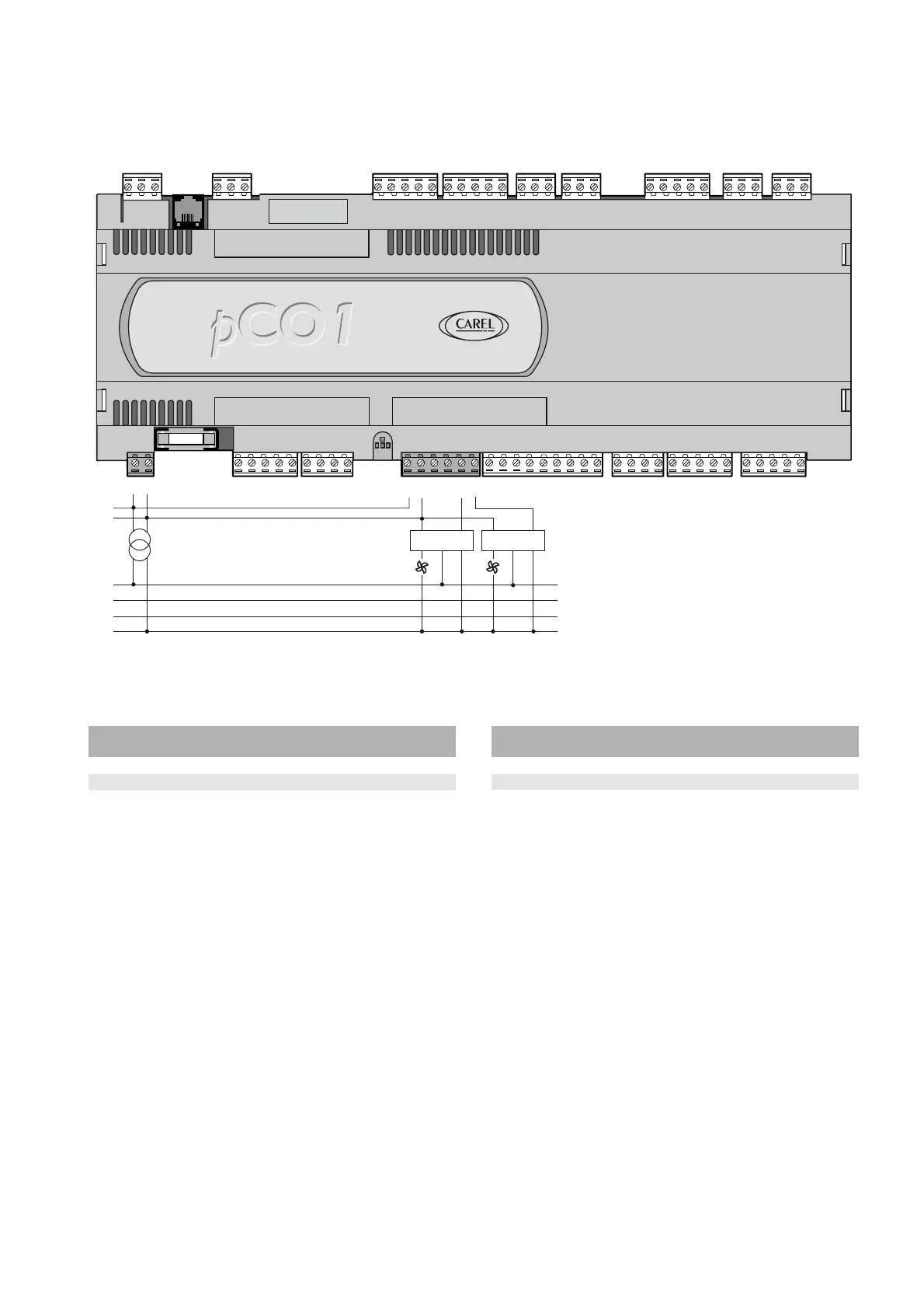
4.7 Collegamento delle uscite analogiche PWM
Il pCO
1
fornisce fino a due uscite analogiche PWM per i regolatori di
velocità a taglio di fase. La Fig. 4.7.1 rappresenta lo schema elettrico di
collegamento. Come si vede il riferimento di fase è lo stesso
dell’alimentazione del pCO
1
G-G0.
La Tab. 4.7.1 riassume la distribuzione delle uscite analogiche in
funzione delle versioni disponibili.
n. uscite n. uscite totale uscite
analog. 0/10 Vdc analog. PWM analogiche
SMALL 2 2
MEDIUM 2 2
Tab. 4.7.1
4.8 Collegamento delle uscite digitali
Il pCO
1
prevede fino a 13 uscite digitali con relè elettromeccanici.
Per facilità d'assemblaggio i morsetti comuni di alcuni relè sono stati
raggruppati. Nel caso in cui si utilizzi lo schema di Fig. 4.8.1.1, la
corrente che interessa i morsetti comuni non deve superare la
portata (corrente nominale) di un singolo morsetto.
I relè sono divisi in gruppi, a seconda della distanza di isolamento.
All’interno di un gruppo, i relè hanno tra loro isolamento singolo e,
quindi, devono essere sottoposti alla stessa tensione (generalmente
24 Vac o 110/230 Vac).Tra i gruppi c’è il doppio isolamento, quindi,
i gruppi possono essere a tensione diversa.
4.7 Connecting the PWM analogue outputs
The pCO
1
provides up to two PWM analogue outputs for phase-cutting
speed controllers. Fig. 4.7.1 shows the electrical connection diagram.
As can be seen, the reference is the same as the power supply to the
pCO
1
, G-G0.
Ta ble 4.7.1 summarises the distribution of the analogue outputs
available according to the version.
no. 0/10Vdc no. PWM total analogue
analogue outputs analogue outputs outputs
SMALL 2 2
MEDIUM 2 2
Table 4.7.1
4.8 Connecting the digital outputs
The pCO
1
features up to 13 digital outputs with electromechanical
relays.
For ease of installation, the common terminals of some of the relays
have been grouped together. If the diagram in Fig. 4.8.1.1 is used, the
current at the common terminals must not exceed the rating
(nominal current) of a single terminal.
The relays are divided into groups, according to the degree of
insulation. Inside each group, the relays have just single insulation and
thus must have the same voltage (generally 24Vac or 110/230Vac).
Between the groups there is double insulation and thus the groups can
have different voltages.
27
pCO
1
manual - cod. +030221840 rel. 1.0 - 09/07/02

 Loading...


