4.5.4 Tabella riassuntiva ingressi digitali in funzione delle versioni
disponibili
AVVERTENZE IMPORTANTI: non collegare altri dispositivi agli
ingressi IDN (ad esempio bobine di relè di rinvio del segnale ad altri
strumenti). Nello specifico caso degli ingressi a 230 Vac è preferibile
porre in parallelo alla bobina il filtro RC dedicato (le caratteristiche
tipiche sono 100 W, 0,5 µF, 630 V); nella Fig. 4.5.3.1 è rappresentata
la sola porzione di pCO
1
riguardante i morsetti descritti.
Se si collegano agli ingressi digitali dei sistemi di sicurezza (allarmi),
si tenga presente quanto segue: la presenza di tensione agli estremi
del contatto va considerata come condizione di normale
funzionamento, mentre tensione assente (nulla) va considerata come
situazione d'allarme. In tal modo viene assicurata anche la
segnalazione di eventuale interruzione (o sconnessione) dell'ingresso.
Le sezioni dei cavi relativamente alla remotazione degli ingressi digitali,
sono riportate nella seguente tabella
sez. (mm
2
) per lunghezze sez. (mm
2
) per lunghezze
fino a 50 m fino a 100 m
0,25 0,5
Tab. 4.5.4.2
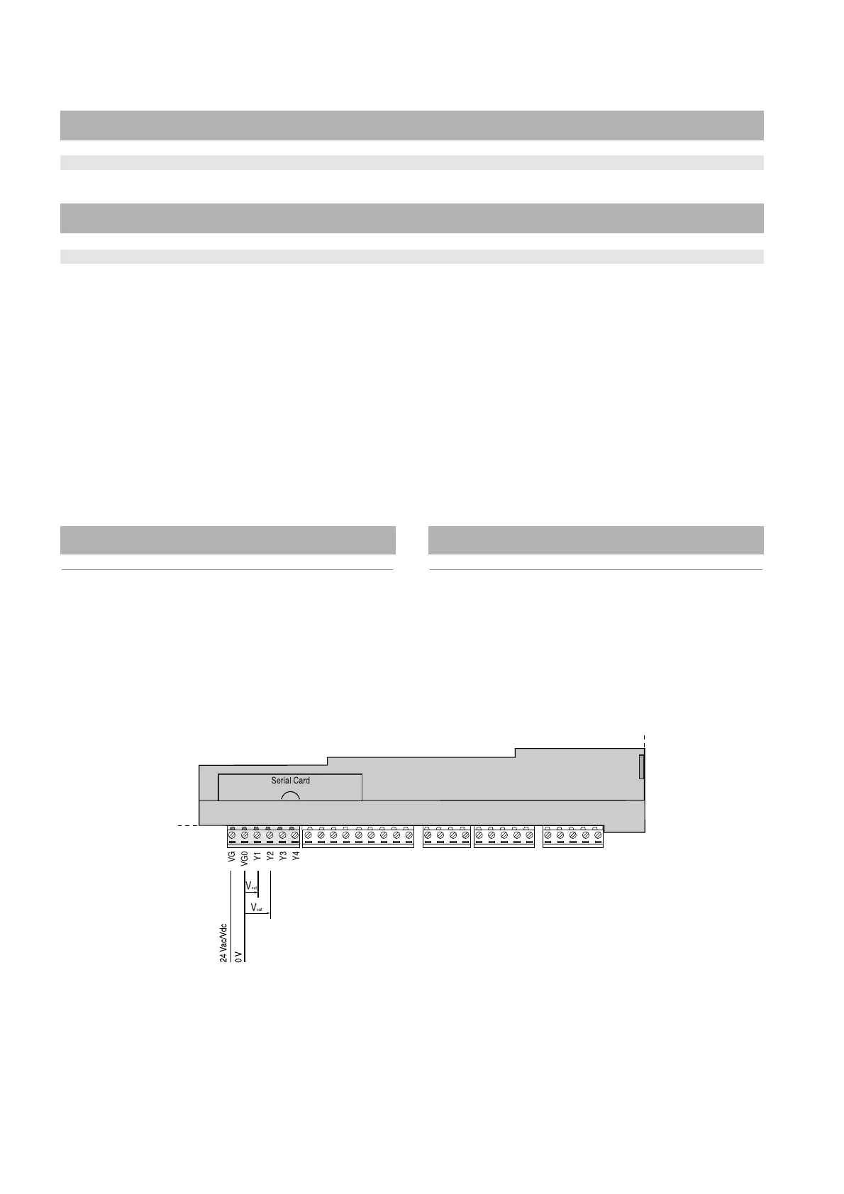
4.6 Collegamento delle uscite analogiche 0/10 Vdc
Il pCO
1
fornisce fino a due uscite analogiche a 0/10 V optoisolate
alimentate esternamente a 24 Vac/Vdc. La Fig. 4.6.1 rappresenta lo
schema elettrico di collegamento; la tensione 0 V (zero)
dell'alimentazione è anche il riferimento di tensione delle uscite.
4.5.4 Table summarising the digital inputs available according to
the version
IMPORTANT WARNINGS: do not connect other devices to the IDN
inputs (for example, relay coils for sending signals to other
instruments). In the specific case of the 230Vac inputs, a dedicated
RC filter (typical characteristics: 100W, 0.5 µF, 630V) should be placed
in parallel to the coil; Fig. 4.5.3.1 shows the part of the pCO
1
involving
the terminals described.
If safety devices (alarms) are connected to the digital inputs, please
keep the following in mind: the presence of voltage at the ends of the
contact is the normal operating condition, while the absence of voltage
is an alarm condition. In this way any interruption (or disconnection) of
the input can be signalled.
When connecting the analogue inputs remotely, the cross section of
the wires must be as shown in the following table
c.sect. (mm
2
) for lengths c.sect. (mm
2
) for lengths
up to 50 m until 100 m
0.25 0.5
Table 4.5.4.2
4.6 Connecting the 0/10Vdc analogue outputs
The pCO
1
provides up to two 0/10V optically-isolated analogue outputs,
powered externally at 24Vac/Vdc. Fig. 4.6.1 shows the electrical
connection diagram; the 0V (zero) of the power supply is also the
reference for the output voltage.
26
pCO
1
manual - cod. +030221840 rel. 1.0 - 09/07/02
n. ingressi optoisolati n. ingressi optoisolati totale
a 24 Vac 50/60 Hz o 24 Vdc a 24 Vac o 230 Vac 50/60 Hz ingressi
SMALL 8 0 8
MEDIUM 12 2 14
Tab. 4.5.4.1
no. of optically-isolated inputs no. of optically-isolated inputs total
at 24Vac 50/60 Hz or 24Vdc at 24Vac or 230Vac 50/60 Hz inputs
SMALL 8 0 8
MEDIUM 12 2 14
Table 4.5.4.1
Fig. 4.6.1

 Loading...


