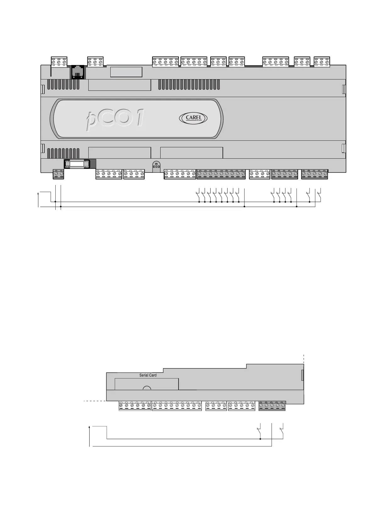
4.5.2 Ingressi digitali alimentati a 24 Vdc
La figura seguente rappresenta uno tra i più comuni schemi di
collegamento degli ingressi digitali a 24 Vdc.
AVVERTENZE IMPORTANTI: nel caso in cui si voglia mantenere
l’optoisolamento degli ingressi digitali è necessario utilizzare
un’alimentazione separata per i soli ingressi digitali. La Figg. 4.5.2.1
rappresenta lo schema di collegamento tra i più utilizzati e tra i più
comodi per la loro realizzazione, non esclude la possibilità di
alimentare gli ingressi digitali in modo indipendente dall'alimentazione
del pCO
1
.
4.5.3 Ingressi digitali alimentati a 230 Vac
La figura seguente rappresenta uno tra i più comuni schemi di
collegamento degli ingressi digitali a 230 Vac. All'interno di ogni gruppo
non si può avere indipendenza degli ingressi digitali: per esempio, con
riferimento alla Fig. 4.5.3.1 gli ingressi ID13 e ID14, a causa del
morsetto comune, devono essere alimentati alla medesima tensione
per evitare pericolosi cortocircuiti e/o messe in tensione a 230 Vac di
circuiti a tensione inferiore.
4.5.2 24Vdc digital inputs
The following figure represents one of the more common connection
diagrams for the 24Vdc digital inputs.
IMPORTANT WARNINGS: to maintain the optical isolation of the digital
inputs, a separate power supply must be used just for the digital inputs;
Fig. 4.5.2.1 shows the connection diagrams, which while being the
more common and the more convenient, do not exclude the possibility
of powering the digital inputs independently from the power supply to
the pCO
1
.
4.5.3 230Vac digital inputs
The following figure represents one of the more common connection
diagrams for the 230Vac digital inputs.Within each group, the digital
inputs are not independent: for example, with reference to Fig. 4.5.3.1,
the inputs ID13 and ID14, due to the common terminal, must be
powered at the same voltage to avoid dangerous short-circuits and/or
the powering of lower-voltage circuits at 230Vac.
25
pCO
1
manual - cod. +030221840 rel. 1.0 - 09/07/02

 Loading...


