La Fig. 5.5.2.2 rappresenta il derivatore
TCONN6J000, utilizzato in coppia per la
remotazione del pCO
1
in rete pLAN con cavo
schermato AWG24.
cavo AWG24 (con alimentazione)
morsetto funzione cavo collegamenti
0terra schermo
1+VRL (≈30 Vdc) 1
o
doppino A
2GND2
o
doppino A
3Rx/Tx-3
o
doppino A
4Rx/Tx+ 3
o
doppino B
5GND2
o
doppino B
6+VRL (≈30 Vdc) 1
o
doppino B Tab. 5.5.2.1
5.5.3 Remotazione terminale con rete pLAN con cavo schermato
AWG20/22
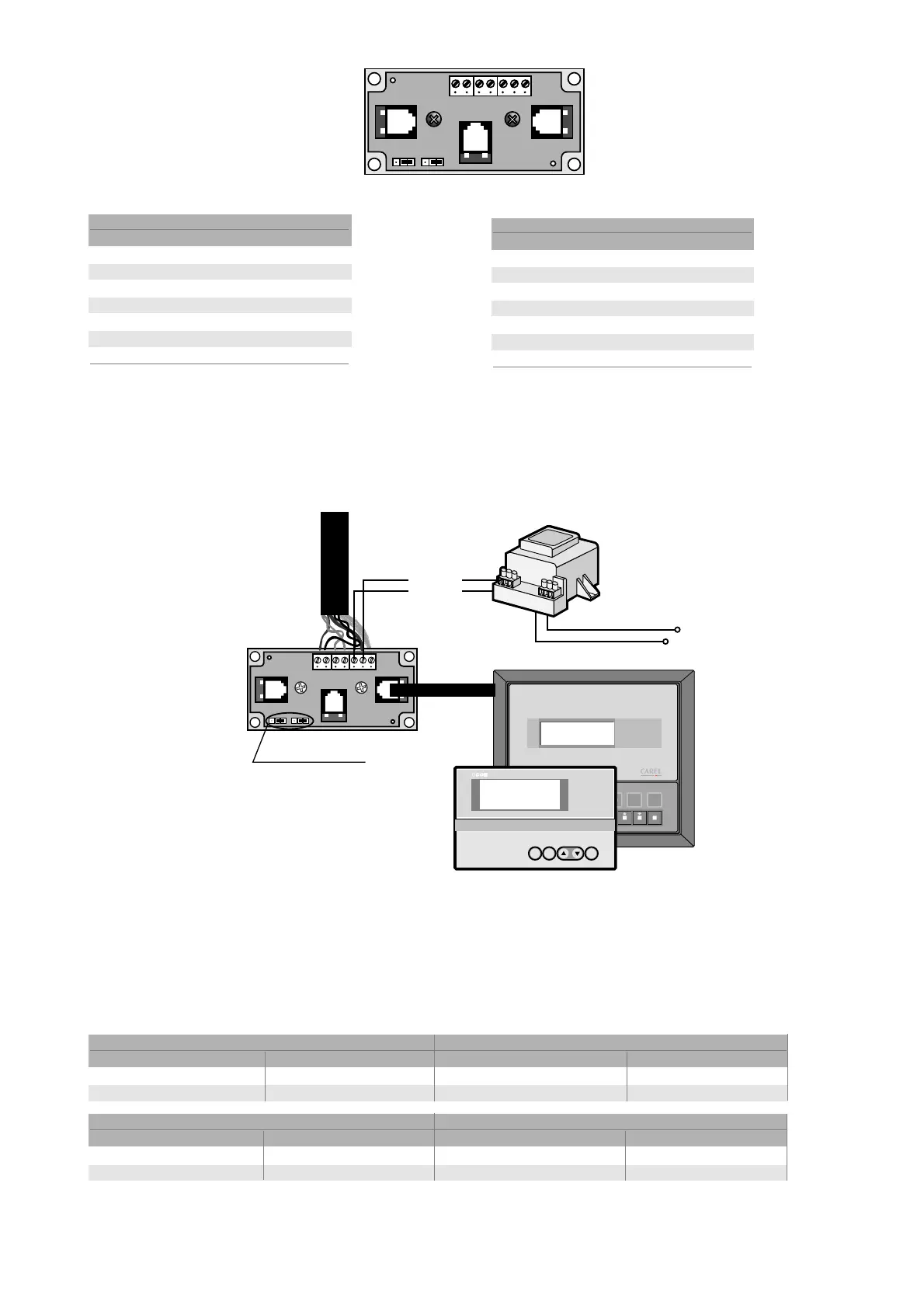
Tale remotazione è rappresentata in Fig. 5.5.3.1, essa prevede
l’alimentazione indipendente del terminale condiviso.
5.5.4 Distanza massima dei collegamenti
Le distanze massime ammesse tra terminale e scheda base (oppure
tra i due dispositivi più lontani connessi in pLAN) sono quelle riportate
nella seguente tabella (Tab. 5.5.4.1)
Fig. 5.5.2.2 represents the shunt TCONN6J000,
used in a pair for the remote installation of the
pCO
1
in a pLAN network with an AWG24shielded
cable.
AWG24 cable (with power supply)
terminal wire function connections
0 earth shield
1+VRL (≈30Vdc) 1st pair A
2GND 2nd pair A
3Rx/Tx-3rd pair A
4Rx/Tx+ 3rd pair B
5GND 2nd pair B
6+VRL (≈30Vdc) 1st pair B Table 5.5.2.1
5.5.3 Remote installation of the terminal in a pLAN network using
an AWG20/22 shielded cable
This type of remote installation is shown in Fig. 5.5.3.1; it requires the
independent power supply of the shared terminal.
5.5.4 Maximum distance of the connections
The maximum distance allowed between the terminal and the main
board (or alternatively between the two furthest apart devices in the
pLAN) are shown in the following table (Table 5.5.4.1)
37
pCO
1
manual - cod. +030221840 rel. 1.0 - 09/07/02
Fig. 5.5.3.1
cavo telefonico cavo schermato AWG24
resistenza del cavo (Ω/m) distanza massima (m) resistenza del cavo (Ω/m) distanza massima (m)
≤ 0,14 600 ≤ 0,078 600
≤ 0,25 400 Tab. 5.5.4.1
telephone cable AWG24 shielded cable
resistance of the cable (Ω/m) maximum distance (m) resistance of the cable (Ω/m) maximum distance (m)
≤ 0,14 600 ≤ 0,078 600
≤ 0,25 400 Table 5.5.4.1

 Loading...


