9.2.3 Uscite analogiche
Il sincronismo per l’uscita PWM taglio di fase è prelevato
dall’alimentazione 24Vac.
9.2.4 Uscite digitali
n. massimo 8, 13 rispettivamente sulle schede: SMALL, MEDIA
tipo a relè elettromeccanici
Tab. 9.2.4.1
9.2.5 Collegamento al terminale utente
tipo asincrono half duplex a 2 fili dedicato
connettore per terminale tipo telefonico 6 vie
connettore per pLAN Connettore estraibile 3 vie
driver differenziale bilanciato CMR 7 V
(tipo RS485)
Tab. 9.2.5.1
9.3 Contenitore plastico pCO
1
Agganciabile su guida DIN secondo Norme DIN 43880 e secondo
Norme EN 50022
Materiale: tecnopolimero
Autoestinguenza V0 (secondo UL94) e 960 °C (secondo IEC 695)
Prova biglia: 125 °C
Resistenza alle correnti striscianti: ≥ 250 V
Colore: grigio RAL7035
Feritoie di raffreddamento
Tab. 9.3.1
9.2.3 Analogue outputs
The synchronicity for the PWM phase-cutting output derives from the
24Vac power supply.
9.2.4 Digital outputs
maximum no. 8, 13 on the SMALL, MEDIUM boards respectively
type electromechanical relays
Table 9.2.4.1
9.2.5 Connection to the user terminal
type asynchronous half duplex, 2 dedicated wires
terminal connector 6 way telephone plug
pLAN connector removable 3 way connector
driver CMR 7 V balanced differential (RS485)
Table 9.2.5.1
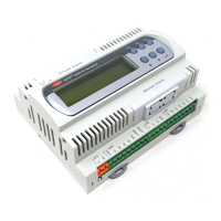
9.3 pCO
1
plastic case
Can be mounted on DIN rail according to DIN 43880 and EN 50022
standards
Material: technopolymer
Self-extinguishing V0 (according to UL94) and 960°C (according to IEC
695)
Marble test: 125°C
Resistance to creeping current: ≥ 250V
Colour: grey RAL7035
Cooling vent
Table 9.3.1
48
pCO
1
manual - cod. +030221840 rel. 1.0 - 09/07/02
Numero massimo e tipo 2 uscite (Y1, Y2) 0/10 Vdc optoisolate e 2 uscite (Y3, Y4) PWM taglio di fase con impulso
a 5 V di durata programmabile
Alimentazione esterna 24 Vac/Vdc
Precisione 1%
Risoluzione 0.5 %
Tempo assestamento uscite analogiche Y1 e Y2 (s) 2
Carico massimo 1 kW (10 mA) per 0/10 V e 470 Ω (10 mA) per PWM
Tab. 9.2.3.1
Maximum number and type 2 x 0/10Vdc optically-isolated outputs (Y1, Y2), and 2 PWM phase cutting outputs (Y3, Y4),
with 5V impulse of programmable duration
Power supply external 24Vac/Vdc
Precision 1%
Resolution 0.5 %
Analogue outputs Y1 and Y2 settling time (s) 2
Maximum load 1 kW (10mA) for 0/10V and 470Ω (10mA) for PWM
Table 9.2.3.1
Gruppi 1, 2, 3, 4, 5, 6, 7, 8 (relè d'allarme) 9, 10, 11, 12, 13
Contatti NO tutti con protezione a varistore da 250 Vac
Contatti in scambio 3 protetti da varistori da 250 Vac su entrambi i contatti
Potenza commutabile 2000 VA, 250 Vac, 8 A resistivi, 2 A FLA, 12 A LRA, secondo UL873 (30.000 cicli)
e relativi parametri elettrici 2 A resistivi, 2 A induttivi, cosϕ=0,4, 2(2) A, secondo EN 60730-1 (100.000 cicli)
Uscite a SSR 2 in alternativa ai relè n° 7 e 8 (SMALL), 4 in alternativa ai relè n° 7, 8, 12 e 13 (MEDIUM); 24 Vac/Vdc, P max= 10 W
Tab. 9.2.4.2
Groups 1, 2, 3, 4, 5, 6, 7, 8 (alarm relay) 9, 10, 11, 12, 13
NO Contacts all with 250Vac varistor protection
Changeover contacts 3 with 250Vac varistor protection on both contacts
Commutable power 2000VA, 250Vac, 8A resistive, 2A FLA, 12A LRA, according to UL873 (30,000 cycles)
and related electrical parameters 2A resistive, 2A inductive, cosϕ=0.4, 2(2) A, according to EN 60730-1 (100,000 cycles)
SSR outputs 2 in alternative to relays 7 and 8 (SMALL), 4 in alternative to relays 7, 8, 12 and 13 (MEDIUM);
24Vac/Vdc, Pmax= 10W
Table 9.2.4.2

 Loading...