15
ENG
µchiller +0300053EN rel. 2.2 - 14.12.2021
Installation
0-10 Vdc probes 4-20 mA probes/digital inputs
J3
0...10Vdc
S4
S6 +
VL
300053_009_R01
300053_011_R01
J3
J2
ID3ID5
ID4S4
S6
VL
S1 S3
S2Y2
Y1ID1
ID2
S5
+V
5V
Fig. 2.i Fig. 2.j
Controller terminals
Pressure probe with current signal
Controller terminals
Pressure probe with current signal
11
+V Power supply brown 5V Power supply black
S1 Signal white O Power reference green
S1 Signal white
Tab. 2.b Tab. 2.c
Notice: O = GND
Notice: if an ExV valve is connected, an NTC temperature sensor must also be connected to read the gas suction temperature:
this sensor must be connected to one of the available inputs provided. For the position of the sensor on the suction pipe, see
the installation guide +040010025 ““Sonde e sensori - Guida alla scelta e all’installazione ottimale / Probes and sensors - Selection
and optimal installation guide”, available at carel.com under product => sensor => quick guide.
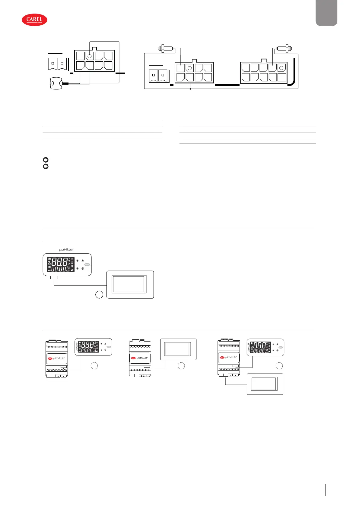
2.6 Connection to user terminals
2.6.1 Panel model
J4
PGDx
1
Fig. 2.k
2.6.2 DIN rail model
PGDx
J8
J4
3
User terminal
J8
J4
2
PGDx
User terminal
J8
J4
4
Fig. 2.l
 Loading...


