16
ENG
µchiller +0300053EN rel. 2.2 - 14.12.2021
Installation
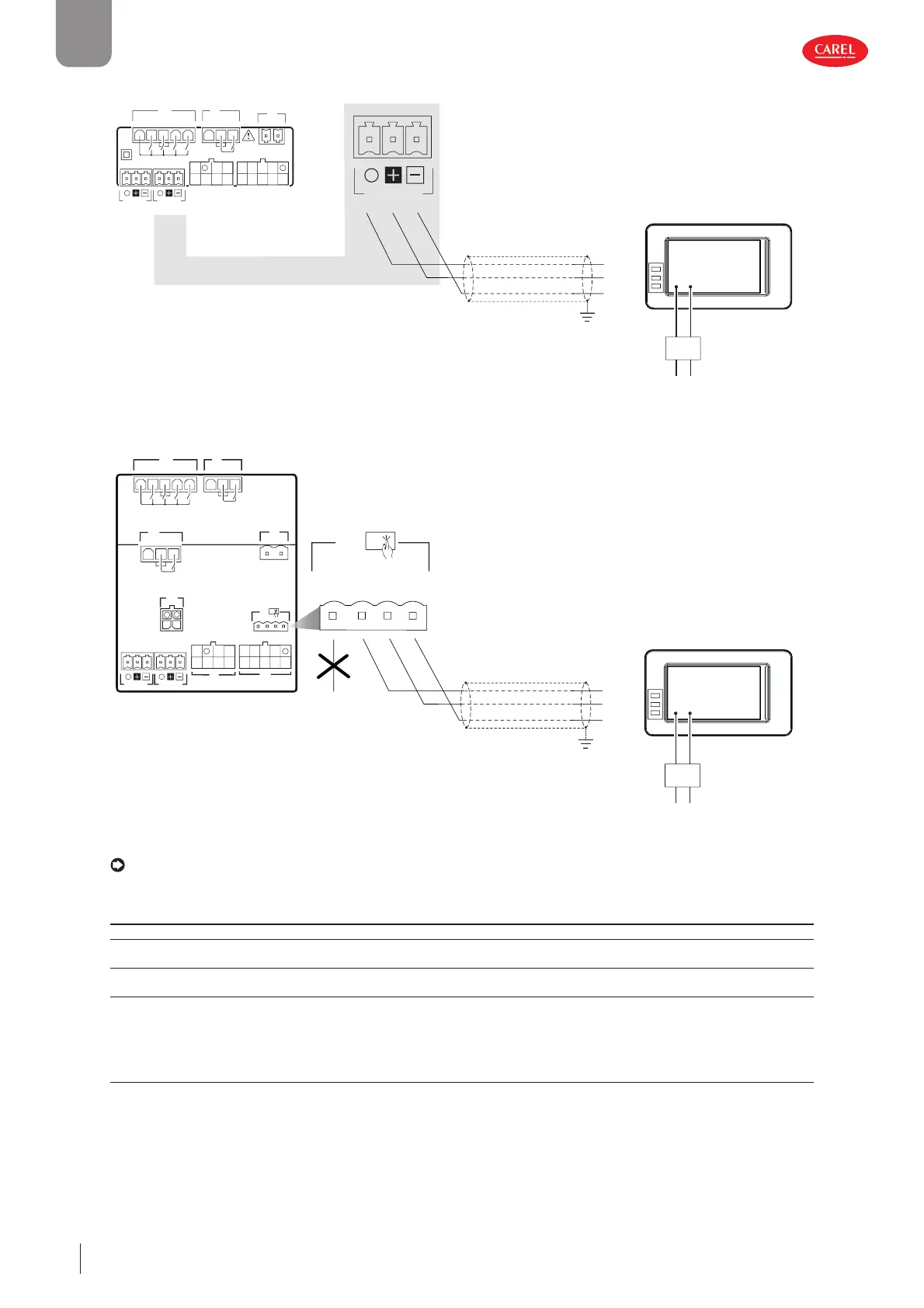
Connection to connector J4
+–
230 Vac
24 Vdc
PSU
PGTA00TRX0
PGDx
shield
Tx/Rx-
Tx/Rx+
GND
J4 BMS
J1
J7
G0 G
J6
C
C
NO1
NO2
NO3
NO4
NO5
J4 BMSJ5 FBus
S1 S3 5V
S2Y2
Y1ID1
ID2
ID3ID5
ID4S4
S6 +V
VL
S5
Fig. 2.m
Connection to connector J8
+–
230 Vac
24 Vdc
PSU
PGTA00TRX0
PGDx
J1
J7
G0 G
J6
C
C
NO1
NO2
NO3
NO4
NO5
J2
J3
J4 BMSJ5 FBus
S1 S3 5V
S2Y2
Y1ID1
ID2
ID3ID5
ID4S4
S6 +V
VL
S5
J11
C NO6
J9
J8
S7ID6
J8
Tx/Rx-
Tx/Rx+
GND
Power
Supply
shield
Tx/Rx-
Tx/Rx+
GND
Fig. 2.n
Notice: (1) and (4) with PGDx connected to port J4 (BMS): the parameters must be set as shown in the following table.
Communication parameters
User Display Code Description Value
S x Hd00 BMS: serial address 1
S x Hd01 BMS: baud rate
3=9600; 4=19200; 5=38400; 6=57600; 7=115200
6
S x Hd02 BMS: settings
0=8-NONE-1; 1=8-NONE-2; 2=8-EVEN-1; 3=8-EVEN-2; 4=8-ODD-1; 5=8-ODD-2
0
Tab. 2.d
2.7 Positioning inside the panel
The position of the controller in the electrical cabinet must be chosen so as to guarantee correct physical separation from the
power components (solenoids, contactors, actuators, inverters, ...) and the connected cables. Proximity to such devices/cables
may create random malfunctions that are not immediately evident. The structure of the panel must allow the correct fl ow of
cooling air.
 Loading...


