55
ENG
µchiller +0300053EN rel. 2.2 - 14.12.2021
Functions
5.3 Frost protection control
Two frost protection control modes are available:
1. using the evaporation pressure probe, which directly monitors the conditions of the evaporator
2. using the water temperature probe to monitor the delivery water temperature or the source water temperature on water/
water units in heating mode).
User Code Description Def Min Max UOM
S U082 Antifreeze controller type 0 = Evaporation temperature 1 = Water temperature 0 0 1 -
5.3.1 Frost protection alarm
When there is a frost alarm on the evaporator, the corresponding circuit is shut down. Each circuit manages its own evaporation
pressure probe, and consequently also the frost protection alarm. The evaporation temperature value is fi ltered based on an
exponential distribution formula that takes into consideration the thermal mass of the evaporator so as to avoid false alarms at
start- up. A specifi c algorithm uses this fi ltered value and activates the alarm if the frost protection threshold is exceeded.
The frost protection alarm reset is set using parameter U081 (see par. 8.1 for further details).
If desired, the frost protection alarm can be set as automatic reset: this means the alarm signal will be cancelled automatically if
the alarm condition is no longer present.
If an evaporation temperature probe is confi gured, frost protection control will automatically using this probe reading, even if
a suction pressure probe is available. If only the suction pressure probe is available, then frost protection control will use the
temperature converted from the pressure reading.
User Code Description Def Min Max UOM
S U050 User side frost protection: alarm threshold -0.8 -99.9 999.9 °C
S U051 User side frost protection: diff erential 30.0 0.0 999.9 K
S U052 User-side frost protection: delay time at 1K 30 0 999 s
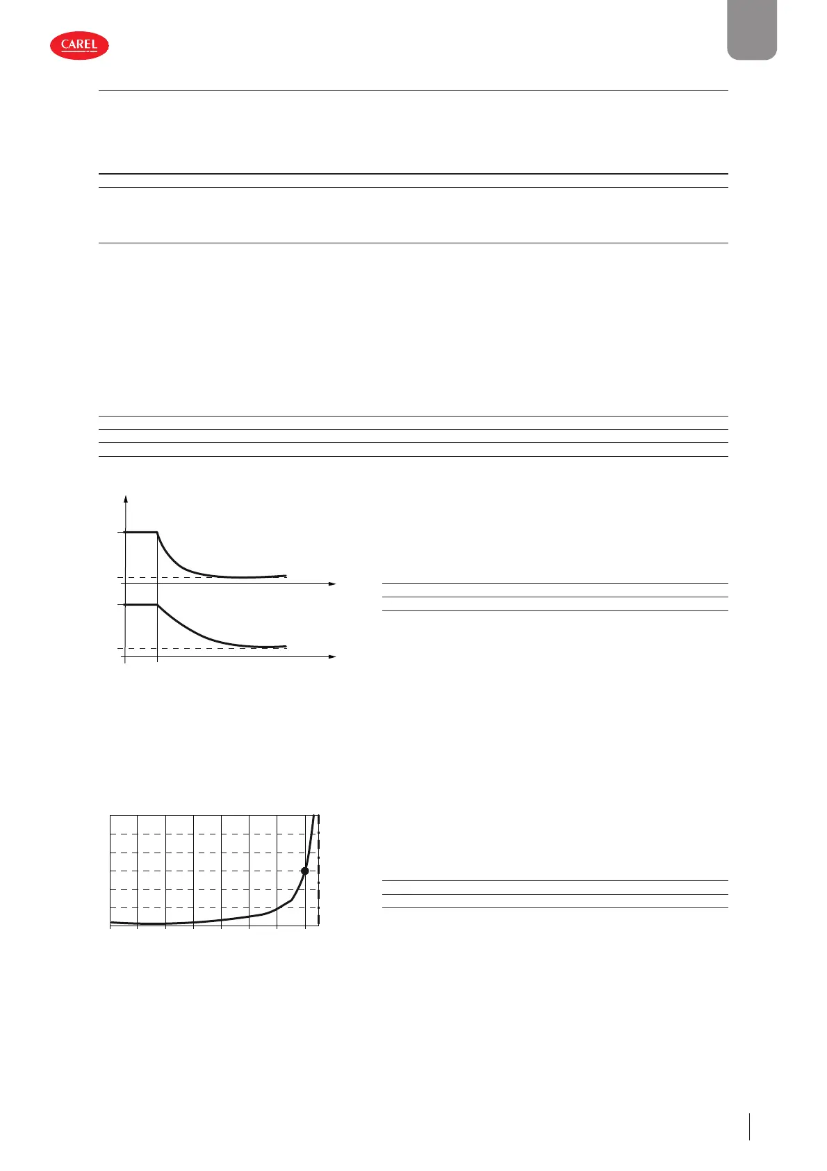
The fi gure shows the action of the fi lter on the evaporation temperature, according to the exponential distribution formula.
300053_054_R01
t (s)
F1
F2
e
°C
Key
Te Filtered evaporation temperature
F1 Filter with low delay
F2 Filter with high delay
Fig. 5.g
When the fi ltered evaporation temperature falls below the alarm threshold, a counter is activated, and the counter time- out is
either increased or decreased based on the deviation of the evaporation temperature from the frost protection threshold, until
reaching zero when the deviation from the threshold it is greater than the diff erential, following a hyperbolic trend. This trend
imitates the actual behaviour of ice formation and ensures better protection. The following diagram shows the trend in the
alarm delay time according to the deviation from the alarm threshold, using the following values: delay time at 1K=60s; diff eren-
tial=30K. At the threshold the delay is equal to 10 times the set value (600s in the example).
300053_055_R01
hrsh
ime (s)
DeltaT (K)
-15 -13 -11 -9 -7 -5 -3 -1
0
20
40
60
80
100
120
Key
Time [s] Frost protection alarm delay
Thrsh Frost protection alarm threshold
DeltaT [K] Deviation from the frost protection alarm threshold
Fig. 5.h
 Loading...


