56
ENG
µchiller +0300053EN rel. 2.2 - 14.12.2021
Functions
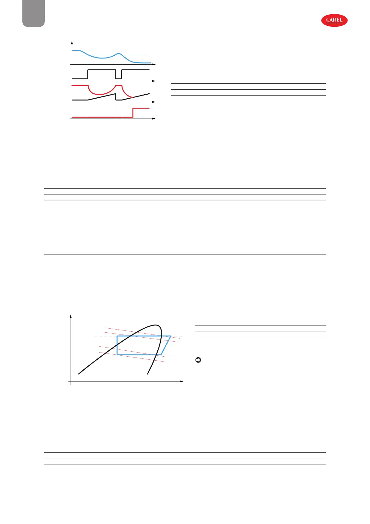
Frost protection alarm operation:
Countdown
hrs
Countdown
active
AL
t (s)
300053_056_R01
Key
t [s] Time [s]
Thrsh Frost protection alarm threshold
AL Frost protection alarm
Fig. 5.i
The value of the delay (at 1K) in the previous example refers to a plate evaporator; if a tube bundle evaporator is used, which has
greater thermal inertia, the delay time (at 1K) can be increased to a suitable value. The following table shows the recommended
values for the alarm threshold (with pure water), diff erential and delay, according to the type of evaporator used.
Code Description
Recommended values based
on the heat exchanger
Tube bundle Plate
U050 User side frost protection: alarm threshold -0.3 °C -1.2 °C
U051 User side frost protection: diff erential 30 °C 30 °C
U052 User-side frost protection: delay time at 1K 90 s 60 s
Tab. 5.f
With pure water, the frost protection threshold must be set just below zero (from - 0.8°C to - 1.5°C) to account for the heat tran-
sfer temperature gradient across the metal between the refrigerant and the water. For tube bundle heat exchangers, values
close to zero (above - 0.5°C) should be considered, to guarantee better protection due to their specifi c mechanical construction.
5.3.2 Frost protection threshold with glide (R407C)
A correct frost protection threshold also needs to consider the minimum temperature reached inside the evaporator. When
using refrigerants without glide or with minimum glide (e.g. R410A, R134a), the value coincides with the pressure-temperature
conversion (dew) of the transducer fi tted on the suction pipe, while for refrigerants with glide (e.g. R407C), the value to be used
is lower than the pressure- temperature conversion (in the case of R407C it is 5- 6°C). The following diagram clearly shows the
diff erence between the two temperature values(Tin and Tout) at the evaporation pressure (Pevap) due to the "glide" eff ect of
the refrigerant.
Enthalpy
Pressure
in
in
out
out
P
cond
P
evap
P-H Diagram - Zeotropic Blend
300053_057_R01
Key
Tin (Pevap) Evaporator refrigerant inlet temperature
Tout (Pevap) Saturated evaporation temperature “dew”
Pcond Condensing pressure
Pevap Evaporation pressure
Note: as a consequence of the above, the suggested
frost protection set point with pure water and R407C refri-
gerant is 4-4.5°C.
Fig. 5.j
5.3.3 Frost protection alarm with water temperature
The frost protection alarm uses the water delivery probe (user) in cooling mode, while in heating mode, on water/water units,
it uses the water temperature. When there is a frost alarm, the corresponding circuits are shut down. When the temperature is
below the alarm threshold, the alarm is activated, and it is reset when it rises back above the threshold plus a diff erential.
User Code Description Def Min Max UOM
S U050 User side frost protection: alarm threshold -0.8 -99.9 999.9 °C
S U051 User side frost protection: diff erential 30.0 0.0 999.9 K
 Loading...


