59
ENG
µchiller +0300053EN rel. 2.2 - 14.12.2021
Functions
300053_058_R01
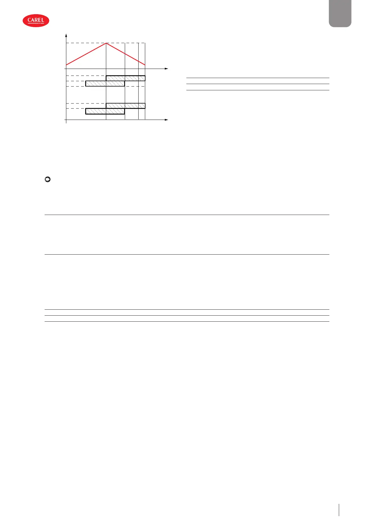
Circuit 2
Request
FIFO
0%
50% 50% 0%100%
C.2
C.1
C.2
C.1
Circuit 1
Key
Request Capacity request (temperature control)
C.1 Compressor 1
C.2 Compressor 2
Fig. 5.k
Capacity distribution with BLDC compressors
If the circuit is equipped with a BLDC compressor, this will always be the fi rst to start and the last to stop. Circuit operation is
modulated so as to meet the capacity request, adjusting BLDC compressor speed and controlling the activation of ON-OFF
compressors.
Note: the confi guration envisaged requires the capacity of the ON/OFF compressor to be equal to 60% of the capacity of
the BLDC compressor (at maximum speed).
5.4.3 Rotation due to alarm
In the event of a compressor alarm, the next compressor available will be switched on as a replacement if the temperature con-
trol request is suffi ciently high as to warrant starting another compressor.
5.4.4 Force rotation (destabilisation)
Some compressor manufacturers specify that on units with multiple compressors, the compressors need to be rotated after a
certain period of inactivity, even if control is stable.
The destabilisation function, which meets this requirement:
• can be enabled by parameter;
• avoids refrigerant migration during long periods of inactivity;
• can also be used to keep all the compressors at operating temperature.
User Code Description Def Min Max UOM
M C020 Maximum circuit destabilisation time 240 5 999 min
M C044 Enable destabilisation - 0/1=No/Yes 101-
 Loading...


