60
ENG
µchiller +0300053EN rel. 2.2 - 14.12.2021
Functions
5.5 Compressor management
Chiller manages scroll compressors with direct starting or modulating BLDC compressors (scroll and rotary).
A maximum of 4 scroll compressors are available in tandem confi guration on two circuits; in the High Effi ciency models, with
BLDC compressors, the maximum is 1BLDC+1On-Off per circuit.
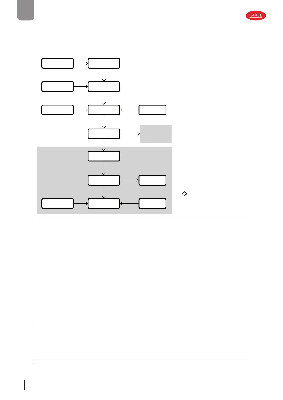
The fl ow chart below shows the process for calculating the request to the compressors:
Unit ON
Pump ON
Thermoregulation
Rotation
Pump-Down
Circuit 1
Circuit 2
Envelope
prevention
Compressor
control
Temperature
control
ExV
Timings
Unit alarms
Flow alarm
BMS
Circuit alarms
0...100.0%
0...100.0%
0...100.0%
0...100.0%
0...100.0%
0...100.0%
OK pump active
OK unit ON
OK
OK
300053_013_R01
Note: for the sake of simplicity, the
parameters are shown for just one
compressor and one circuit, therefore
all the compressors and circuits on the
unit will have the same settings.
Fig. 5.l
5.5.1 Prede ned BLDC compressors
The type of BLDC compressor can be chosen from the list of compressors available on KSA (ksa.carel.com), Chiller section.
When selecting a specifi c type of compressor, the following parameters are set based on the compressor manufacturer’s tech-
nical specifi cations:
1. compressor motor:
– all the characteristic electrical parameters of the compressor motor;
– minimum and maximum frequency settings, acceleration and deceleration ramps.
2. compressor envelope:
– all the characteristic points that defi ne the shape of the compressor envelope;
– maximum discharge temperature (compressor outlet).
3. compressor envelope management:
– MOP and pressure diff erence (DeltaP), minimum ExV opening parameters;
– working point control parameters;
– prevention parameters.
5.5.2 Safety times
Chiller guarantees compliance with compressor safety times, such as:
• minimum on time;
• minimum off time after deactivation request from controller;
• minimum time between consecutive starts.
User Code Description Def Min Max UOM
M C012 Min compressor on time 180 30 999 s
M C013 Min compressor off time 60 30 999 s
M C014 Min time between consecutive compressor starts 360 300 999 s
 Loading...


