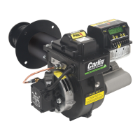
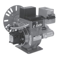
Model 201CRD & 301CRD Advanced oil burners — Instruction manual
Carlin part number MN2301 Rev. 04/12/04
– 8 –
Inspect burner and components
General
• Check the air tube length. Verify the usable length of the tube UTL will be
long enough (see “Mount burner in appliance”).
• Visually inspect all burner components and wiring.
• Verify that wiring is intact and leads are securely connected.
• Verify that all burner components are in good condition.
Do not install or operate the burner if any component is
damaged or if burner does not comply with other guidelines
of this manual and the appliance manual.
Install/check burner flange
Welded-flange burners
1. Verify the bolt pattern on the appliance chamber matches the flange pat-
tern.
2. Verify the insertion depth (UTL) matches the depth of the appliance open-
ing (so the end of the air tube is flush with, or slightly short of, the inside
surface of the combustion chamber).
Burners with adjustable flanges
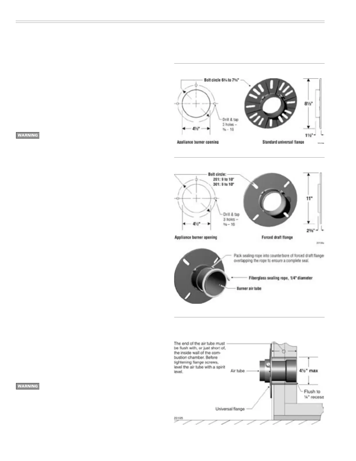
1. See Figure 2 for standard adjustable flange (universal flange) dimensions.
See Figure 3 for adjustable forced draft flange dimensions.
Verify the flange mounting slots line up with the appliance bolts.
2. Slip the adjustable flange onto the air tube.
3. Measure the distance from the inside of the combustion chamber to the
outside of the appliance mounting plate.
4. Position the adjustable flange at this distance from the end of the air
tube.
5. Tighten the locking screws finger tight.
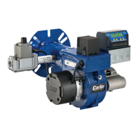
6. Insert the air tube/flange assembly into the appliance opening and level
the air tube with a spirit level (see Figure 4). Adjust flange if needed.
7. The end of the air tube should be flush, or almost flush, with the inside of
the combustion chamber wall.
8. Verify the air tube is level and inserted the correct depth. Adjust if necessary.
Then tighten the flange locking screws securely.
9. Remove the flange/air tube assembly from the opening.
10. Forced draft adjustable flanges: Use ¼-inch diameter fiberglass sealing
rope, as shown in Figure 3, to seal the flange to the air tube.
A forced draft adjustable flange must be sealed to the air
tube to prevent possible leakage of flue products. Failure
to comply could result in severe personal injury, death or
substantial property damage.
Figure 2 Standard adjustable flange (universal flange)
Figure 4 Mark insertion depth on air tube when using universal
flange mounting
2. Prepare site • assemble burner • mount burner (continued)
Figure 3 Adjustable forced draft flange