BT2 user manual - H-5911-9004-02-B Page | 115
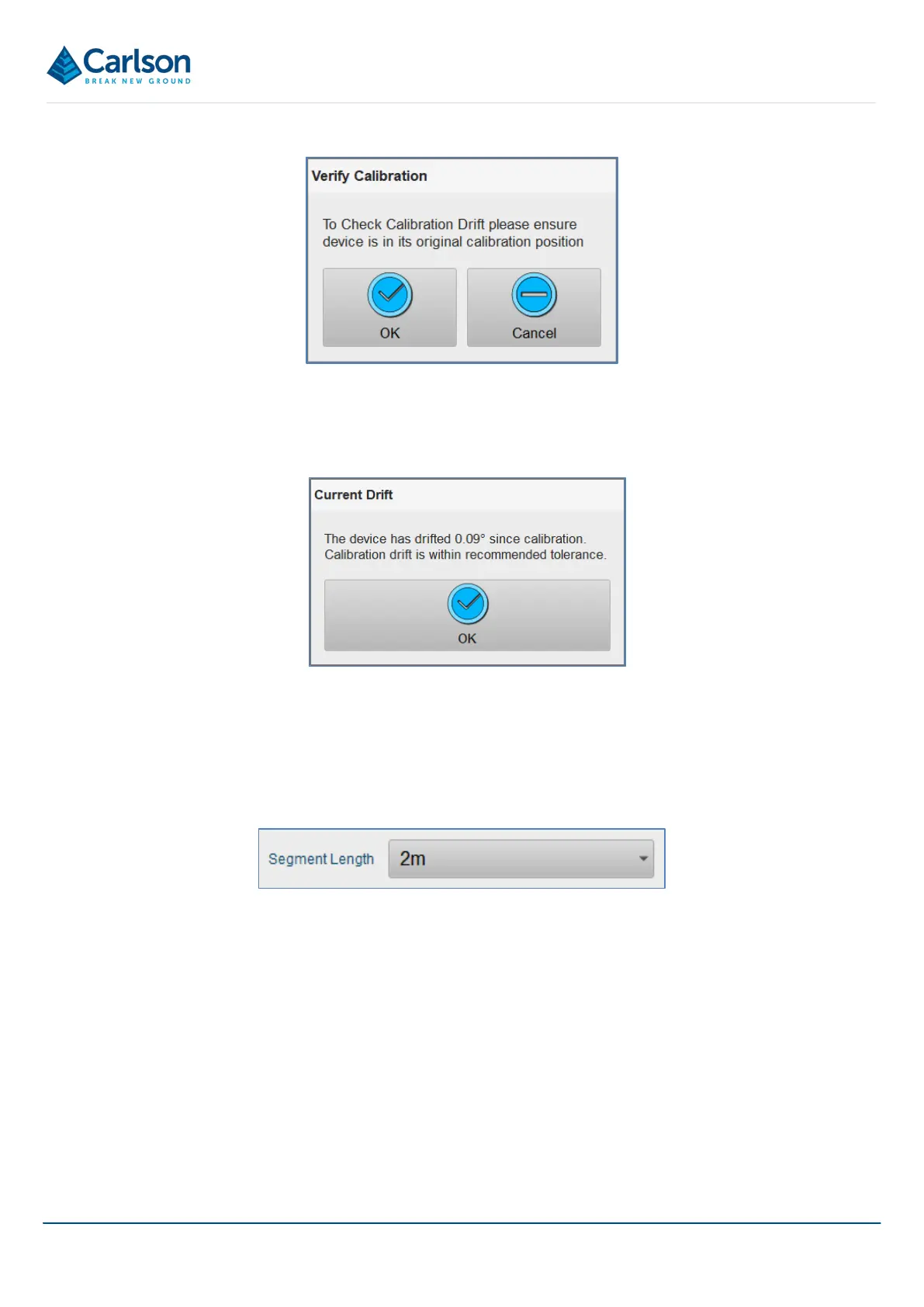
Place the probe back on the jig, in the same orientation. The jig must not have been moved since the last alignment.
Tap OK. The current heading is compared to the user-defined alignment heading from the last alignment.
15.4.5 Segment length
During most deployments, the Boretrak2 probe is lowered at fixed intervals. At each interval, the probe is held
steady while a Boretrak reading is taken. Use the Segment length drop-down to define this deployment increment.
In the drop-down list are three options
• 1 m.
• 2 m: this is the default for the first reading taken in a deployment.
• Custom: this activates the number-pad so that you can enter a user-defined distance.
The selected option cannot be changed after a deployment has been started.
15.5 Live display
The Live display shows data from the probe’s sensors and from the deployment.
Figure 130 Segment length
Figure 128 Verify Alignment
Figure 129 Alignment Drift