4
ELECTRICAL
For proper wiring connections, consult the wiring diagram located
inside the compressor terminal box cover and Fig. 2 for wiring
connection locations. Refer to Fig. 2-4 for terminal plate
components.
Fig. 2 — Terminal Box Arrangement
Terminal Box
All UL recognized 06CC compressors have terminal enclosures
that are suitable for outdoor use equipment as a sole enclosure.
The compressor terminal box is supplied with a support plate to
mount the connector for the power wiring conduit. The support
plate can be fastened to the terminal box with the (4) screws pro-
vided.
Terminal Plate Wiring
The parts listed in Table 1 are supplied in a parts bag with the
compressor and are used when wiring the terminal plate. Refer to
Step 4 in the General section on page 1 and Table 1. Customer
supplied wiring to the compressor terminal plate must be provided
with insulated wire terminal connectors and be suitable for accom-
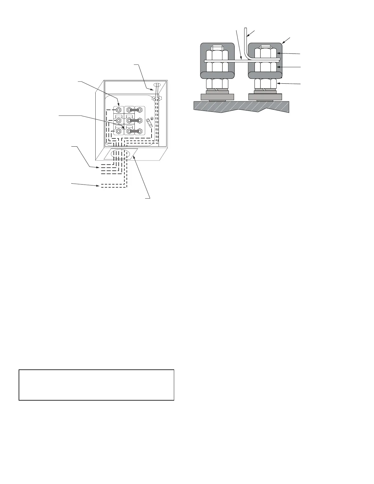
modating the 3/8 in. diameter terminal studs. Figure 3 shows the
wiring components of the terminal plate. Jam Nut No. 1 is factory-
installed and should not be disturbed. Jam Nut No. 2 should be in
contact with the underside of the jumper bar or ring terminal if no
jumper bars are used. Jam Nut No. 2 should be installed finger
tight, never torqued with a wrench. Jam Nut No. 3 should be in
contact with the upper side of the jumper bars or ring terminal and
should be wrench torqued.
Fig. 3 — Terminal Plate Components
6-PIN TERMINAL PLATE3-LEADACROSS-THE-LINE (XL)
START
See Fig. 4A.
6-PIN TERMINAL PLATE3-LEADVARIABLE SPEED
See Fig. 4G.
Install (3) 2-hole copper jumper bars directly on top of Jam Nut
No. 2, connecting terminals T
1
to T
7
, T
2
to T
8
, and T
3
to T
9
.
1. Connect the line leads directly on top of the jumper bars to
terminals T
1,
T
2
, and T
3
.
2. Install (6) Jam Nut No. 3 (included in this kit) on terminal
studs to secure jumper bar/line connections. Tighten Jam Nut
No. 3 to 18 lb-ft (24 Nm) maximum.
6-PIN TERMINAL PLATE6-LEADACROSS-THE-LINE (XL)
START
Not shown in Fig. 4.
1. Install (3) 2-hole copper jumper bars directly on top of Jam
Nut No. 2, connecting terminals T
1
to T
7
, T
2
to T
8
, and T
3
to
T
9
.
2. Connect the line leads directly on top of the jumper bars to
terminals T
1
, T
2
, T
3
, T
7
, T
8
, and T
9
.
3. Install (6) Jam Nut No. 3 (included in this kit) on terminal
studs to secure jumper bar/line connections. Tighten Jam Nut
No. 3 to 18 lb-ft (24 Nm) maximum.
6-PIN TERMINAL PLATE6-LEADPART WINDING (PW)
START
See Fig. 4D.
1. Jumper bars are not required with 6-Lead PW start applica-
tions. Jam Nut No. 2 should be finger tightened only, do not
torque with wrenches.
2. Connect the part winding start leads directly on top of Jam
Nut No. 2 to terminals T
1
, T
2
, and T
3
.
3. Connect the full winding run leads directly on top of Jam Nut
No. 2 to terminals T
7
, T
8
, and T
9
.
4. Install (6) Jam Nut No. 3 (included in this kit) on terminal
studs to secure jumper bar/line connections. Tighten Jam Nut
No. 3 to 18 lb-ft (24 Nm) maximum.
IMPORTANT: Variable speed applications should refer to
the Variable Speed Compressor Supplemental, 574-087 for
electrical details that are specific to variable speed applica-
tions
Factory-Supplied Wiring To
Cylinder Head Temp Sensor
3/8 in.-16 Terminal Studs
For Motor Connections
(T
4
T
5
and T
6
are present only
in the 9-pin terminal plate.)
Customer Supplied
Wiring To Motor
Connections
Jumper Bars
(See wiring diagrams for
configuration details.)
Customer Supplied
Wiring To Sensor
Connections
Factory-Supplied
Adapter Plate For
Conduit Connection
1 7
2 8
3 9
4
5
6
1
2
3
1
2
3
Jam Nut No. 1
Jam Nut No. 3
Jam Nut No. 2
Ring Terminal
Jumper Bar
Insulator
NOTE: Jumper bars not required in all installations. Refer to Fig. 5
for usage.
 Loading...


