5
9-PIN TERMINAL PLATE ACROSS-THE LINE (XL)
START208/230V-3-60/200V-3-50
See Fig. 4B.
9-PIN TERMINAL PLATE VARIABLE SPEED
208/230V-3-60/200V-3-50
See Fig. 4H.
1. Remove plastic connector block from terminals T
4
, T
5
,
and T
6
.
2. Install the flat connector block (non-conducting) on
terminals T
4
, T
5
, and T
6
.
3. Reinstall Jam Nut No. 2 on terminals T
4
, T
5
, and T
6
(removed in Step 2). Finger tighten only; do not torque with
wrenches.
4. Install the 3-hole copper jumper bar directly on top of Jam
Nut No. 2, connecting terminals T
4
, T
5
, and T
6
.
5. Install (3) 2-hole copper jumper bars directly on top of Jam
Nut No. 2, connecting terminals T
1
to T
7
, T
2
to T
8
, and T
3
to T
9
.
6. Connect the line leads directly on top of the jumper bars to
terminals T
1
, T
2
, and T
3
.
7. Install (9) Jam Nut No. 3 (included in this kit) on terminal
studs to secure jumper bar/line connections. Tighten Jam
Nut No. 3 to 18 lb-ft (24 Nm) maximum.
9-PIN TERMINAL PLATEPART WINDING (PW) START
208/230V-3-60/200V-3-50
See Fig. 4E.
1. Remove plastic connector block from terminals T
4
, T
5
,
and T
6
.
2. Install the flat connector block (non-conducting) on termi-
nals T
4
, T
5
, and T
6
.
3. Re-install terminal nuts on terminals T
4
, T
5
, and T
6
(removed in Step 1). Finger tighten only, do not torque with
wrenches.
4. Install the 3-hole copper jumper bar directly on top of Jam
Nut No. 2, connecting terminals T
4
, T
5
, and T
6
.
5. Connect the line leads directly on top of the jumper bars to
terminals T
1
, T
2
, T
3
, T
7
, T
8
, and T
9
.
6. Install (9) Jam Nut No. 3 (included in this kit) on terminal
studs to secure jumper bar/line connections. Tighten Jam
Nut No. 3 to 18 lb-ft (24 Nm) maximum.
9-PIN TERMINAL PLATE ACROSS-THE LINE (XL)
START460V-3-60/400V-3-50
See Fig. 4C.
9-PIN TERMINAL PLATEVARIABLE SPEED460V-3-60/
400V-3-50
See Fig. 4I.
1. Install (3) 2-hole copper jumper bars connecting terminals
T
7
to T
4
, T
8
to T
5
, and T
9
to T
6
.
2. Connect the line leads directly on top of the jumper bars to
terminals T
1
, T
2
, and T
3
.
3. Install (9) Jam Nut No. 3 (included in this kit) on terminal
studs to secure jumper bar/line connections. Tighten Jam
Nut No. 3 to 18 lb-ft (24 Nm) maximum.
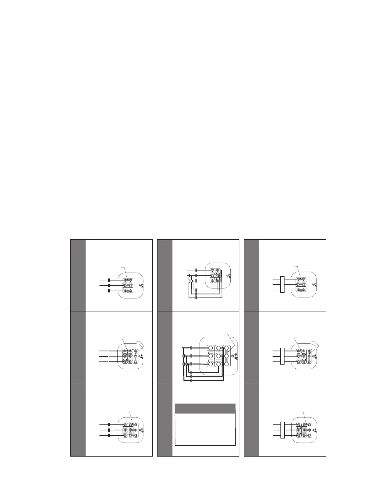
Fig. 4 — Terminal Plate Wiring Schematic
6-PIN TERM PLATE
DISCRETE VOLTAGE
3-LEAD XL START
A
9-PIN TERM PLATE
208/230/460V DUAL VOLTAGE
208/230V 3-LEAD XL START
B
L1
L2
L3
JUMPER BARS
(2 HOLE)
9-PIN TERM PLATE
208/230/460V DUAL VOLTAGE
460V 3-LEAD XL START
C
6-PIN TERM PLATE
DISCRETE VOLTAGE
6-LEAD PW START
D
9-PIN TERM PLATE
208/230/460V DUAL VOLTAGE
208/230V PW START
E
9-PIN TERM PLATE
208/230/460V DUAL VOLTAGE
460V PW START
F
WARNING
208/230/460V MODELS
CANNOT BE WIRED FOR
460V PART WIND START.
USE DISCRETE 460V MOTORS
FOR ANY 460V PART WIND
APPLICATIONS.
6-PIN TERM PLATE
3-LEAD VARIABLE SPEED
460V, 575V
G
9-PIN TERM PLATE
3-LEAD VARIABLE SPEED
208/230V
H
9-PIN TERM PLATE
3-LEAD VARIABLE SPEED
460V
I
1 7
2 8
3 9
4
5
6
L1
L2
L3
JUMPER BARS
(2 HOLE)
1 7
2 8
3 9
4
5
6
VFD
L1
L2
L3
Jumper Bars
(2 Hole)
1 7
2 8
3 9
L1
L2
L3
JUMPER BARS
(2 HOLE)
1 7
2 8
3 9
VFD
L1
L2
L3
1 7
2 8
3 9
1 7
2 8
3 9
4
5
6
L1
L2
L3
JUMPER BAR
(3 HOLE)
4
5
6
L1
L2
L3
JUMPER BARS
(2 HOLE)
(3 Hole)
71
82
3 9
4
5
6
L1
L2
L3
JUMPER BARS
(2 HOLE)
(3 HOLE)
71
82
3 9
VFD
 Loading...


