27
All Paragon compressors come equipped with an
infinitely adjustable slide valve unloading system. The
actual capacity reduction will depend on the system oper-
ating conditions and the rebalance characteristics.
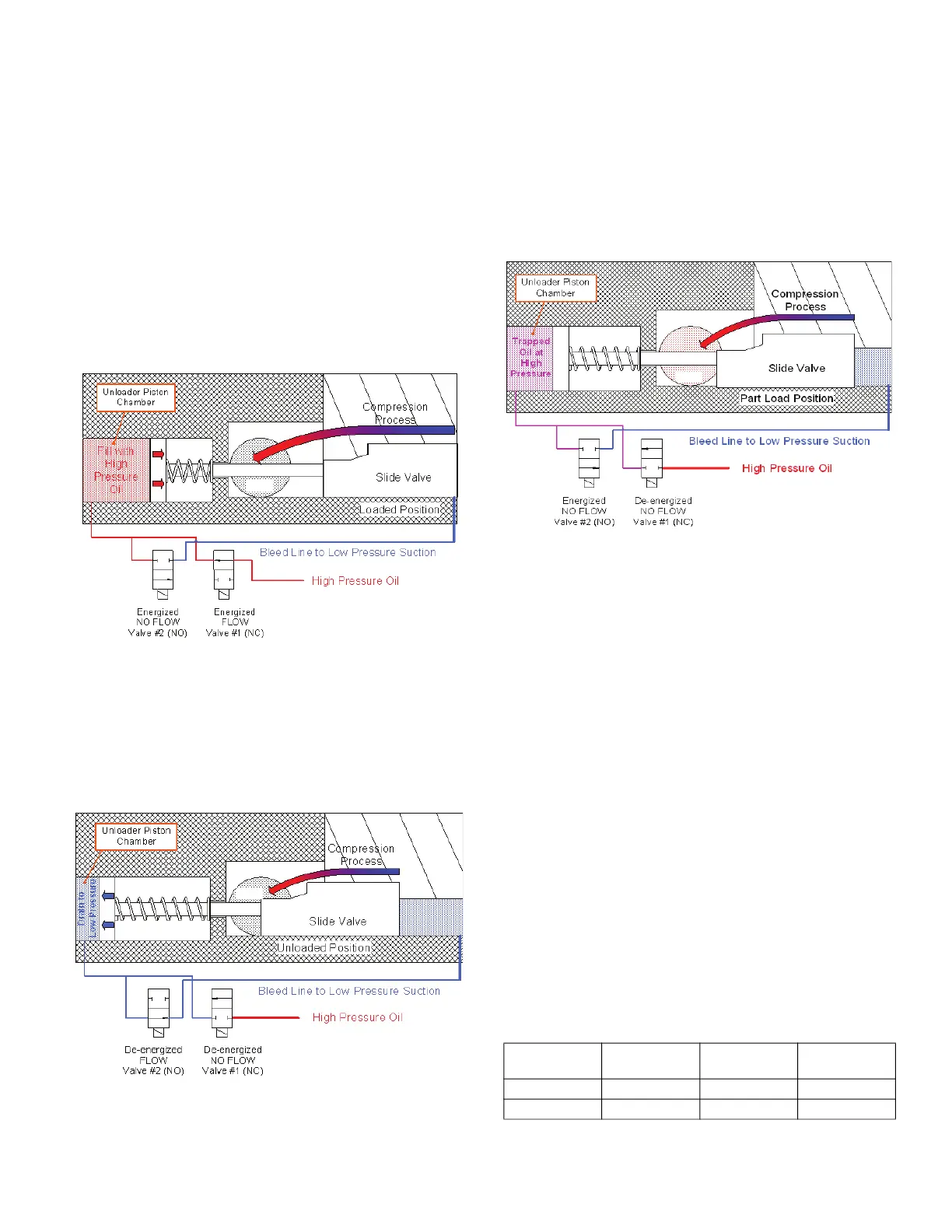
Two solenoids control the slide valve by allowing commu-
nication between the unloader piston chamber and either
high pressure oil or low pressure suction.
• To fully load the compressor, bot
h solenoid #1 and #2
are energized (see Fig. 19). This allows high-pressure
oil to enter the unloader piston chamber, moving the
slide valve and providing more engagement under the
screw rotors. Both solenoids should remain energized
to maintain the full load position.
• To unload the compressor, both solenoids are de-
energized (Fig. 20). This exposes the unloader piston
chamber to suction pressure, pulli
ng the slide valve
out from under the screw rotors and reducing the
amount of compression being performed.
.
• Part load is achieved by stopping the load or unload
process previously described at an intermediate slide
valve position. Stopping the valve at an intermediate
position is accomplished by de-energizing valve #1
and energizing valve #2 (Fig. 21). When this happens,
both valves are closed and the pi
ston is not allowed to
move. Cycling of the solenoids may be required to
compensate for leakages around the piston seal, etc.
The TU and TV water-cooled models have a hot gas
bypass port on the slide valve. This feature allows dis-
charge gas to leak back to suction through the slide valve
when the slide valve is in the fully unloaded position. The
hole is closed at all other load states. The purpose
of this
feature is to allow the compressor to unload to 15% of the
full load capacity.
The compressor will start with minimum power draw in
the fully unloaded state. There is no minimum or maxi-
mum time limit immediately after start-up for which the
compressor must operate in the unloaded state. How-
ever, it is recommended that the compressor operates
unloaded for a minimum load for 30 seconds ju
st prior to
shutdown. This will ensure the compressor is fully
unloaded on the subsequent start, and means that the
compressor is drawing the minimum current when the
contactors open to shut down the compressor.
5.1 Unloader System Control Points
Table 10 shows the proper control states for the slide
valve solenoids. See Fig. 22 for solenoid locations.
Table 10 — Proper Control States for
Slide Valve Solenoid
s
* Maintain capacity: Solenoid activation after proper slide valve position
has been attained.
Fig. 19 — Fully Loaded Operation
Fill with
High
Pressure
Oil
DISCHARGE
PORT
Fig. 20 — Configuration for Unloading
DISCHARGE
PORT
Drain to
Low Pressure
INCREASE
CAPACITY
DECREASE
CAPACITY
PARTIAL*
SOLENOID #1 Energized De-Energized De-Energized
SOLENOID #2 Energized De-Energized Energized
Fig. 21 — Configuration for Maintaining Part Load
DISCHARGE
PORT
5.0 Unloader Operation
 Loading...


