28
5.2 Approximate Part Load Factors
Table 11 shows the typical relation of part load capacity
and power at their respective rating conditions. Contact
Carlyle Application Engineering for further information.
Table 11 — Typical Relation of Part Load Capacity
Certain fully unloaded operating conditions may result in
discharge gas temperatures which exceed the recom-
mended operating parameters. Carlyle requires
that
some form of liquid injection be applied to control/reduce
discharge gas temperatures to be within recommended
guidelines. Common methods to accomplish this may
include increased flow through the economizer circuit or
direct liquid injection into the economizer port/tubing.
5.3 Slide Valve Capacity Controller and Pro-
tection
5.3.1 General Description
The Carlyle Control Module (CCM) will function to control
compressor capacity by operating the compressor's slide
valve to maintain the system's control set point (suction
pressure or temperature). This process control point is an
input to the CCM. In addition, the CCM will have function-
ality to protect the compressor and provide LED fault sta-
tus indication for:
• Oil Level Protection
• Oil Flow Protection
• Motor Cooling Protection
• Discharge Temperature Protection
• Transducer Sensor Failure
• Temperature Thermistor Failure
The following Paragon capacity and protection kits
6BSB000929 and 6
BSB000930 are available through
Carlyle. See Table 12. Detailed information regarding the
Paragon Slide Valve controller may be found at www.car-
lylecompressor.com, Application Guide 575-012.
5.3.2 CCM Configuration
The CCM can be configured to function in the following 3
modes of operation:
1. Slide Valve Control and Compressor Protection
(Default Setting).
2. Slide Valve Control only.
3. Compressor Prot
ection only.
Configuring the CCM for options 2 or 3 can be accom-
plished through:
• Using the BACview
1
hand-held display unit.
• Downloading BACview software to a laptop.
• Setting up a communication port between the CCM
and System Controller.
To allow easier transmission of data across a network
between the CCM and the System Controller, the CCM is
pre-configured with the following protocol networks:
• BACnet
2
• Modbus
3
• N2 Open
• LonWorks
4
(requires optional card)
• RS485 Communication Port
Table 12 — Paragon Capacity and Protection Kits
% FULL
LOAD
CAPACITY
AIR-COOLED (R-134a) WATER-COOLED (R-134a)
% FULL LOAD POWER % FULL LOAD POWER
100 10
0 100
75 78 78
50 58 58
34 50 50
15 — 50
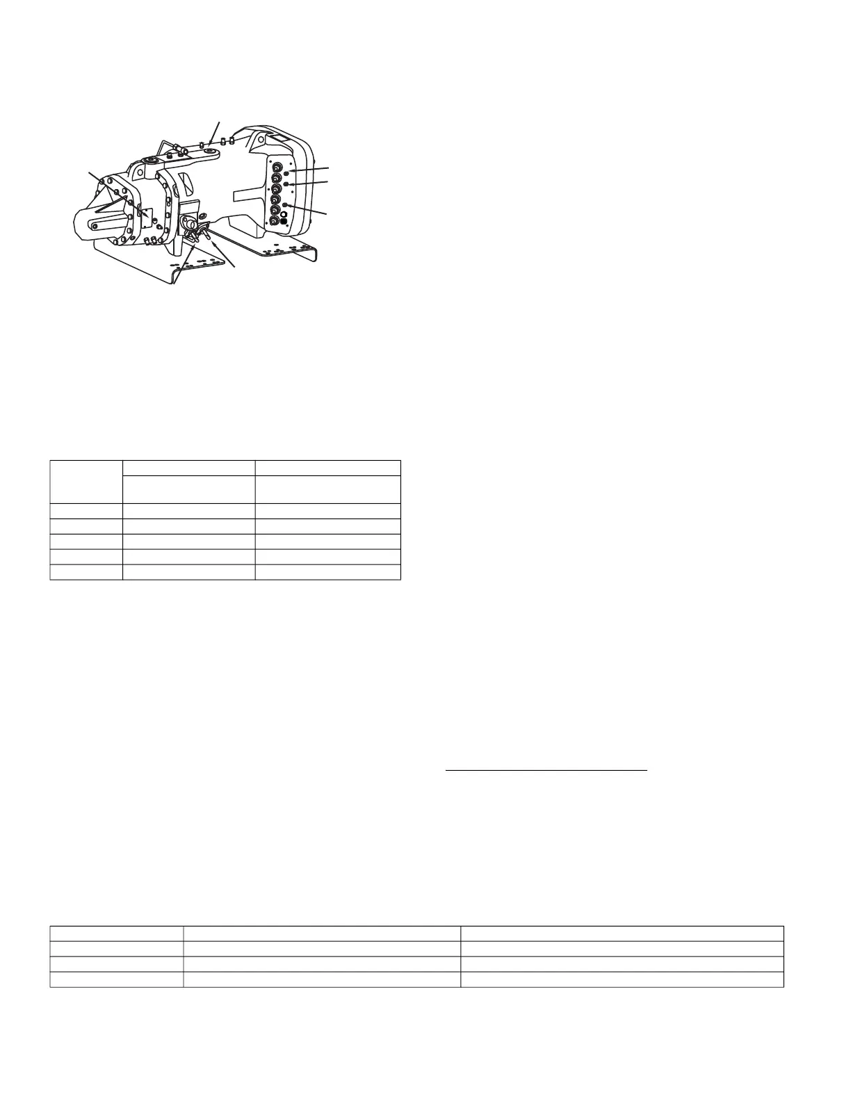
Fig. 22 — Solenoid Locations
SOLENOID 1
SOLENOID 2
HIGH PRESSURE
SWITCH
MOTOR
TEMPERATURE
SENSOR 2
COMMON
MOTOR
TEMPERATURE
SENSOR 1
SUCTION
TEMPERATURE
1. BACview is a registered trademark of Automated Logic
Corporation.
2. BACnet is a registered trademark of ASHRAE (American
Society of Heating, Refrigeration and Air-Conditioning
Engineers).
3. Modbus is a registered trademark of Schneider Electric.
4. LonWorks is a registered trademark of Echelon Corporation.
CARLYLE P/N DESCRIPTION APPLICATION
6BSB000929 High Temperature Paragon Controller Kit R-134a, R513A
, R1234ze
6BSB000930 Low/Medium Temperature Paragon Controller Kit R404A, R-407A, R-407C, R-407F, R-448A, R-449A, R-507A
USB-L CCM Interface Cable Cable interface between controller and laptop
 Loading...


