GB-9
ENGLISH
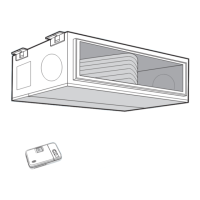
INSTALLING THE UNIT
Important: the unit must be correctly
levelled.
Insert the 4 M8 threaded tie rods into the
ceiling. Insert the other end of the tie rods
through the slots in the hanging brackets
on the sides of the unit. Position the anti-
vibration dampers, add the washers and
tighten the nuts until the unit is correctly
fixed and levelled. If space permits, place a
layer of rubber or neoprene between the
ceiling and the unit.
On completion of these operations it is
necessary to:
• install a suspended ceiling to conceal the
unit;
• include a removable panel for future
maintenance work;
• fit suitably sized grilles in the suspended
ceiling to allow air intake.
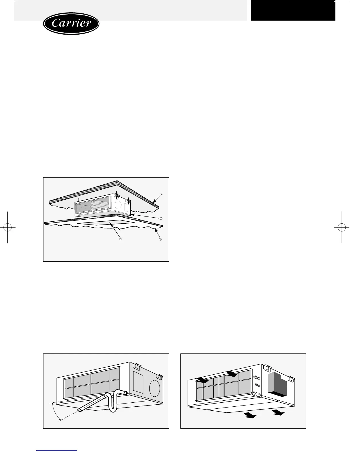
CONDENSATE DRAINAGE
Important: do not lift the unit by means
of the condensate drain pipe.
All units are equipped with a condensate
collection tray with 21 mm external Ø drain
pipe.
Therefore fit a pipe for the evacuation of
condensate.
Adhere to the following recommendations:
• Use pipes in galvanised steel, copper or
transparent plastic. Do not use normal gar-
den hoses.
• Use material which ensures that the drain
pipe connections are totally sealed.
• If using rigid material for the outlet pipe, fit a
number of flexible couplings to absorb any
vibrations from the unit.
• The drainage line must always be below
the connection itself, with a suitable gradi-
ent to facilitate outflow.
• Pour a few litres of water into the conden-
sate collection tray and check that it flows
out correctly. If not, check the gradient of
the pipes and look for possible obstruc-
tions.
INTAKE CONFIGURATION
Important: units configured for intake
from below must not be installed at a
height of less than 2.5 m from the
ground.
The unit is factory-configured for air intake
from the rear.
Unit
Suspended ceiling
Ceiling
Removable cover
Minimum gradient 5%
 Loading...


