GB-13
ENGLISH
The area of the panel which can be used
for fixing the 8” circular flanges (not sup-
plied) is as shown in the figure. Avoid
drilling or fastening screws in the shaded
area of the figure so as not to damage the
unit’s tray.
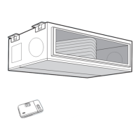
Installation with side outlet
The unit is predisposed so that it can be
installed in corridors to make optimum use
of the two circular outlets on the sides. In
order to prepare the unit for this type of
installation, proceed as follows:
remove the two cut-outs in the sides of the
unit.
After removal, make certain that the insula-
tion covers the steel sheet around the cut
area.
The area which can be used for fixing the
8” circular flanges (not supplied) is as
shown in the figure.
Avoid drilling or fastening screws in the
areas highlighted in the figure so as not to
damage the unit’s tray.
Replace the front panel of the unit with the
panel supplied.
60 mm
60 mm
 Loading...


