22
SW2-COM
SW2-AUTO
SW2-CONT
ECM
ECM
1
2
3
4
5
6
7
8
9
3
1
23
CBC2
1
Relative
Humidity
Sensor
AIR
QUALITY
SENSOR
SEN
SET
NO
NC
NO
NC
NO
NC
T36
T35
T33
T32
T31
T30
T29
T28
T26 24 Vdc
K3
Optional Wall Mount
Space Temp. Sensor
w/Setpoint Adjust.
ENTHALPY
SWITCH
RED
RED
RED
J1
Power
BRN
3
1
2
J4
Service
J3
CCN
T34
T39
T38
T37
T1
T2
T3
T4
T5
T6
T7
T8
T9
T10
T11
T12
T13
T14
T15
T16
SFS T17
unused T18
OA Enth T19
R S/S T20
FSD T21
LTT T22
CHGOVR T23
Spare DI T24
Common T25
RAT
SAT
MAT
OAT
BLK/21
VIO VIO VIO
VIO
BRN
BLK
ORN
WHT
BLK
WHT
GRN
K2 K1
BLU
BLU
BLK
BLK
RED
BLK
RED
RED
BLK
WHT
BLK
WHT
NOTE 2
(Field Installed)
Field Supplied -
Dedicated 24 VAC
NOTE 2
NOTE 1 NOTE 1
BLK
WHT
RED
WHT
WHTBLK
RED
Field Supplied/
Installed options
TB2
CLOSE
24 V
COM
OPEN
BLK
RED
(Optional)
SPT
SAT
MAT
OAT
SPT ADJ
Spare AI
AQ
RH/Spare
OAC
1
2
3
LL
VIO/2
BLU/1
ORN/3
3
2
1
BRN
BLK
RED
BRN
4
VIO/2
BLU/1
ORN/3
BLK
WHT
ORN
YEL
BLU
VIO
1
2
3
4
5
6
7
8
9
10
11
12
CBC2
RED
BRN
RED
11
12
CBC3
WHT
BLK
8
ORN/38ORN
6
VIO VIO/36
7
5
1
BLU BLU/37
WHT/35WHT
BLK
CBC2
5
WHT
4
5
BRN
RED
ORN
YEL
BLK
GRA
GRA
1
2
3
4
5
6
7
8
9
CBC3
CBC1
RED
ORN
YEL
BLK
GRA
WHT
BLU
VIO
BRN
RED
ORN
YEL
BLK
GRA
WHT
BLU
VIO
BLK
RED
CBC3
4
YEL
2
RED
3
YEL
6
YEL
RED
RED
Cooling
Output
Heating
Output
OA
Damper
Output
Heating
Enable
Cooling
Enable
7
ORN
YEL
8
YEL
BLU
RED
RED
VIO
BLU
VIO
4
5
GRN
FIRE/SMOKE
DETECTOR
NOTE 4
499 ohm
RED/FSD
NOTE 5
24 V (gnd)
24 V (hot)
V2C
YEL
RED
BRN
NOTE 3
ORN
CLOSE
24 V
COM
OPEN
2
3
6
1
V1C
BLU
RED
BRN
VIO
2
3
4
1
See Detail A for
Steam Valve Wiring.
VIO
RED
BRN
NOTE 3
BLU
V1C
VIO
RED
BRN
NOTE 3
BLU
Y1-CLS
G0-24V
G-COM
Y2-OPN
1000 ohm
1000 ohm
2
3
4
1
RESISTOR HARNESS
2
3
4
1
Detail A - STEAM VALVE WIRING
CLOSE
24 V
COM
OPEN
OCC/UNOCC
RED
ORNORN
24
OA damper not installed on
Recirculation Only Units.
FROM CONTROL BOX
OUTDOOR
AIR DAMPER
CW VALVE
HW VALVE
RED
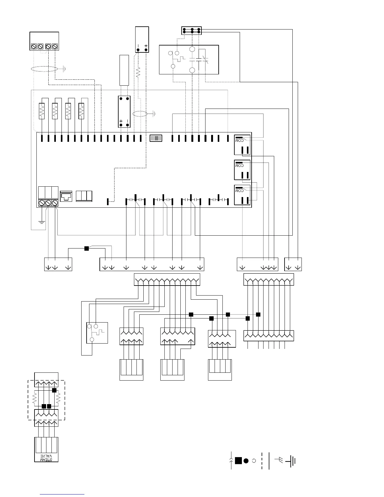
Fig. 8B — Unit Ventilator Wiring with CCN Controls — Control Diagram (115 vac)
NOTES:
1. When factory installed, optional wall-mount space sensor is wired to provide set point adjustment only. When remote sensor installation is field required, disconnect
the factory-supplied return air sensor and wire as shown.
2. Use shielded wire when field installing these parts. Connect the drain wire to the unit chassis and insulate the sensor end. Factory wiring consists of unshielded wire.
3. Hot water (HW) valve opens on loss of power. Chilled Water (CW) valve closes on loss of power.
4. See power diagram for CBC1 wiring.
5. Wire RED/FSD factory wired to TB2. When field installing a fire/smoke detector, remove RED/FSD from TB2 and wire as shown.
LEGEND
AQ — Air Quality
CCN — Carrier Comfort Network®
CGOVR — Changeover
COM — Common
CW — Chilled Water
ECM — Electronically
Commutated Motor
GND — Ground
HW — Hot Water
LL — Low Limit Device
MAT — Mixed Air Temperature
NC — Normally Closed
NO — Normally Open
OA — Outdoor Air
OAT — Outdoor Air Temperature
OCC/
UNOCC
— Occupied/Unoccupied
RAT — Return Air Temperature
RH — Relative Humdity
SAT — Supply Air Temperature
SPT — Space Temperature
SPT ADJ — Space Temperature
Adjustment
Harness Connection
Connection Point Splice
Splice Terminal Connection
Component Tie Point
Optional Wiring
Factory Wiring
Chassis Ground
Earth Ground
 Loading...


