38
CHANGEOVER SWITCH (Factory-Installed Option) —
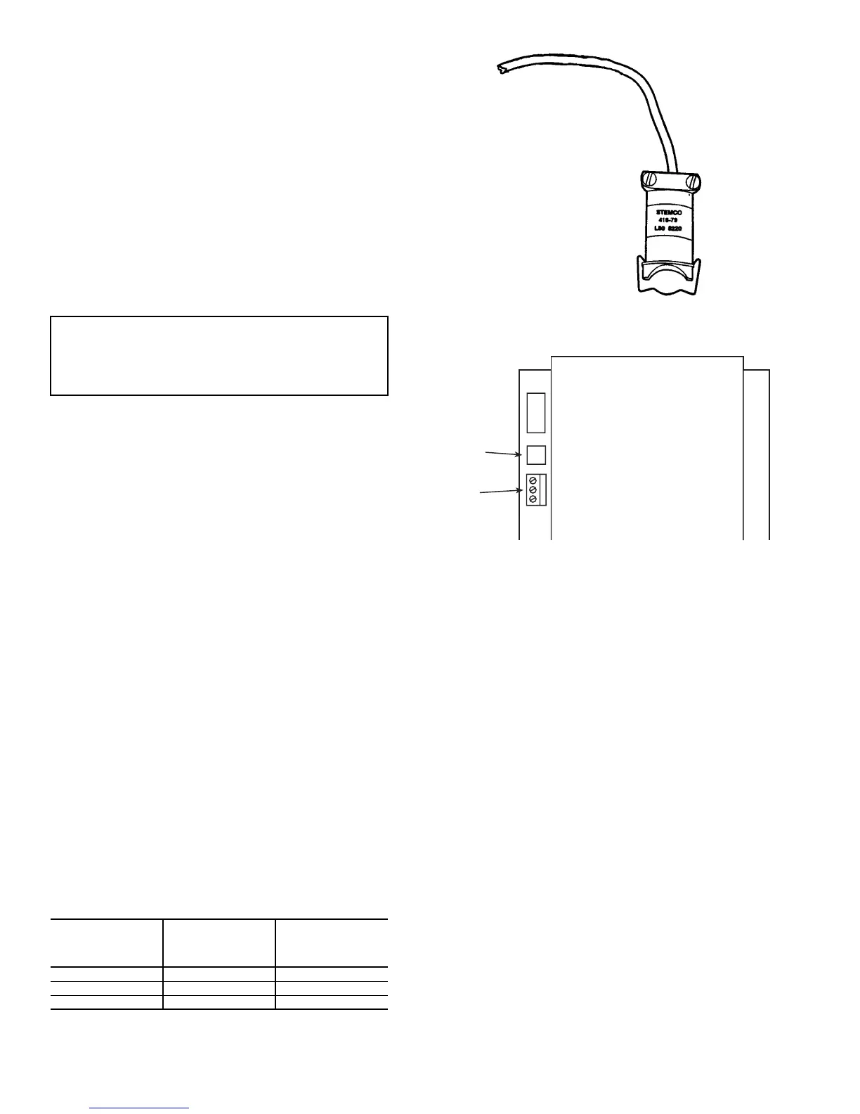
The changeover switch is used with 2-pipe changeover units to
determine if the temperature of the water in the water loop can
provide cooling or heating (Fig. 25). The switch provides this
input to the control. The changeover switch is factory-wired to
the control and ready for field mounting to the water piping.
The switch mounts to the water pipe using a spring-loaded
clamp.
It is primarily used for a stand-alone application, although
the changeover switch may be required for CCN applications if
the water temperature status is not available through the
network. For stand-alone applications, one switch is required
for each 2-pipe unit. If the units are connected together on a
3-wire CCN communication bus and a linkage thermostat
(or Unit Ventilator Comfort Control module [P/N 110500])is
used, then a single switch can be connected to any one unit and
the linkage thermostat can be configured to broadcast the
switch status to all other units.
FILTER/SMOKE STATUS (CCN Systems Only) — The
filter/smoke status is monitored by the control module and
contains an adjustable alarm limit. The control accumulates
fan-operating hours; when the total hours exceed the limit, an
alarm is generated.
The alarm limit is adjustable from 100 to 9900 hours. It is
factory preset to 1500 operating hours. The limit is normally
field adjusted and is dependent on the filter media used as well
as the quality and amount of outdoor air required. The normal
range is from 400 to 1500 hours.
Carrier Comfort Network® Interface — The Carrier
Comfort Network (CCN) communication bus wiring is
supplied and installed by the electrical contractor. It consists of
shielded, 3-conductor cable with drain wire.
The system elements are connected to the communication
bus in a daisy-chain arrangement. The positive pin of each
system element communication connector must be wired to the
positive pins of the system element on either side of it; the
negative pins must be wired to the negative pins; the signal
ground pins must be wired to signal ground pins. See Fig. 26
for location of the CCN communication connector (NET-
WORK) on the control module.
NOTE: Conductors and drain wire must be 20 AWG mini-
mum, stranded tinned copper. Individual conductors must be
insulated with PVC, PVC/nylon, vinyl, Teflon, or polyethyl-
ene. An aluminum/polyester 100% foil shield and an outer
jacket of PVC, PVC/nylon, chrome vinyl, or Teflon with a
minimum operating temperature range of –20 C to 60 C is
required. See Table 14 for cables that meet the requirements.
When connecting the CCN communication bus to a system
element, a color code system for the entire network is recom-
mended to simplify installation and checkout. The following
color code is recommended:
If a cable with a different color scheme is selected, a similar
color code should be adopted for the entire network.
At each system element, the shields of its communication
bus cables must be tied together. If the communication bus is
entirely within one building, the resulting continuous shield
must be connected to ground at only one point. See Fig. 27. If
the communication bus cable exits from one building and en-
ters another, the shields must be connected to ground at the
lightning suppressor in each building where the cable enters or
exits the building (one point only).
To connect the control to the network, proceed as follows
(Fig. 27):
1. Turn power to the control box OFF.
2. Remove the CCN connector from the control board.
3. Cut the CCN wire and strip the ends of the RED,
WHITE, and BLACK conductors.
4. Using a wire nut, connect the 2 drain wires together.
5. Insert and secure the 2 RED wires to terminal 1 of the
CCN connector.
6. Insert and secure the 2 WHITE wires to terminal 2 of the
CCN connector.
7. Insert and secure the 2 BLACK wires to terminal 3 of the
CCN connector.
8. Replace connector on control board.
9. Turn on power to control box.
IMPORTANT: The switch must be mounted on the
supply water pipe, where water flows continuously to
accurately sense the available water temperature. Never
mount the sensor on piping which is connected to a
2-way valve.
SIGNAL
TYPE
CCN BUS
CONDUCTOR
INSULATION
COLOR
CCN
CONNECTOR
+ RED 1
Ground WHITE 2
– BLACK 3
POWER
SERVICE
NETWORK
CCN
CONNECTOR
RJ-14
SERVICE
JACK
Fig. 25 — Changeover Switch
Fig. 26 — CCN Communication Connector
 Loading...


