27
Table 10 — Control Board Terminal Designations
LEGEND
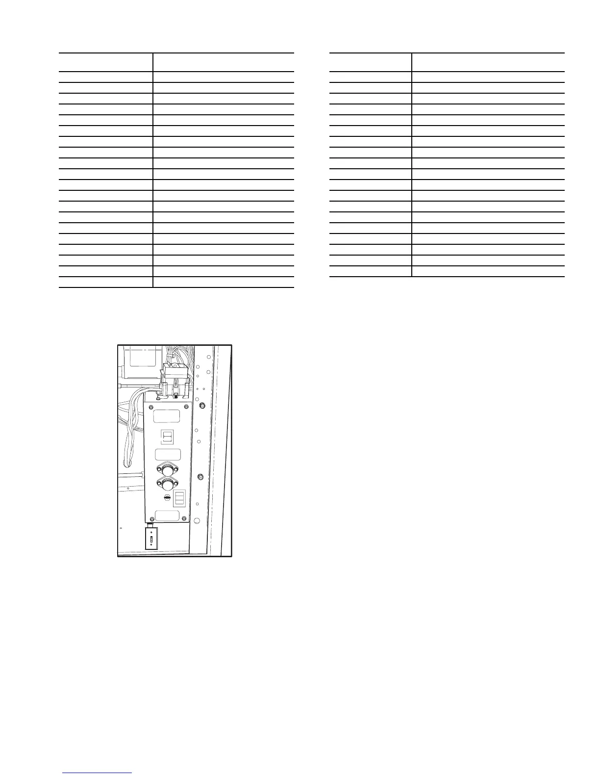
Unit Ventilator Comfort Control Module Instal-
lation and Field Wiring —
The module is factory-
installed and factory-wired within the control compartment.
The Unit Ventilator Comfort Control module contains the soft-
ware and microprocessor that operates the unit. It continuously
monitors inputs and controls outputs such as the fan cooling
and heating coil valves and dampers. Refer to Fig. 11 for
wiring diagram connections between the unit’s sensors and
actuators and the control module. Direct expansion cooling
and/or electric heat stage control are also provided.
CONTROL BOARD
TERMINAL
FUNCTION
T1 Space Temperature (+)
T2 Space Temperature (Gnd)
T3 Supply-Air Temperature (+)
T4 Supply-Air Temperature (Gnd)
T5 Mixed-Air Temperature (+)
T6 Mixed-Air Temperature (Gnd)
T7 Outdoor-Air Temperature (+)
T8 Outdoor-Air Temperature (Gnd)
T9 Space Temperature Adjust (+)
T10 Space Temperature Adjust (Gnd)
T11 Not Used
T12 Not Used
T13 Air Quality (+)
T14 Air Quality (Gnd)
T15 Relative Humidity (+)
T16 Relative Humidity (Gnd)
T17 Fan Status
T18 Not Used
T19 Outdoor Air Enthalpy
T20 Remote Start/Stop
CONTROL BOARD
TERMINAL
FUNCTION
T21 Fire/Smoke Status
T22 Freezestat
T23 Changeover
T24 Spare
T25 Common/Ground
T26 24 VDC (External Power Supply)
T27 Not Available
T28 Cooling First Stage or Valve Open
T29 Cooling Common
T30 Cooling Second Stage or Valve Close
T31 Heating First Stage or Valve Open
T32 Heating Common
T33 Heating Second Stage or Valve Close
T34 OAD Open
T35 OAD Common
T36 OAD Close
T37 Heating Enable
T38 Common
T39 Cooling Enable
Gnd — Ground
OAD — Outdoor-Air Damper
ON
OFF
HI
LOW
MAX
Fig. 10 — Control Switch Location