46
SET-UP, CONFIGURATION, AND
OPERATION
The Unit Ventilator Comfort Control module (P/N 110500)
is designed to be installed using the CCN Network Service
Tool, or a CCN Building Management system such as Building
Supervisor, ComfortVIEW™ or ComfortWORKS® software.
The control provides several comprehensive screens for easy
set-up and configuration of the control. See Tables 23-29. Two
additional screens display the operation of the equipment.
Each unit is factory-configured for the control sequence or-
dered. Only set points, schedules, alarm limits, and user op-
tions need to be adjusted. Tables 23-29 depict the screens that
provide a list of the information contained within each func-
tion, the expected range of values for each parameter, and the
allowable force limits or configuration range. For specific in-
formation about Network Service Tool, Building Supervisor,
ComfortVIEW, or ComfortWORKS software refer to the oper-
ating instructions for each specific piece of software.
The Service Configuration screens are used to specify the
equipment model and control sequence being used, such as the
type of heating or cooling used (chilled water, DX cooling,
steam, or hot water) and the damper control type (ASHRAE
Cycle I, II or III). These values are factory-configured for the
control sequence as ordered. A separate configuration screen is
used to modify the factory pre-configured alarm set points, if
required, in order to meet a specific customer requirement.
The service configuration screens are located under the
Diagnostic/Service Configuration function. See Table 24.
Alarm configurations are shown in Table 25.
The Modify controller screen allows the installer to select
from a list of standard control options which can be used for
specific applications. Standard control options include Space
Temperature Set Point adjustment with an adjustable maxi-
mum limit, the ability to provide dehumidification with or
without reheat, override duration, unoccupied free cooling, or
warm up temperature check, and other control features.
The control configuration screens are located under the
CCN Configuration function. See Table 27.
The Set Point screen is used to configure the desired control
set points for the specific application. These set points include
the occupied heating and cooling set points, the unoccupied
heating and cooling set points, the ventilation airflow set point,
the IAQ set point (optional) and the ASHRAE Cycle III Damp-
er set point (for Cycle III control). The Set Point screen is locat-
ed under the Modify/Set Points function. See Table 28.
The Points/Display screen is used to monitor equipment
operation and provides a simple overview including: the oper-
ating mode, heating and cooling capacity, ventilation airflow
value, equipment and sensor alarms, and a list of actual sensor
and output values. The Status Display screen is located under
the Points/Display function. See Table 26.
The Maintenance screen provides an indication of the
control algorithm operation and a view of each individual con-
trol loop as it is currently functioning. The Maintenance
screens are located under the Diagnostic/Maintenance func-
tion. See Table 29. The Linkage Maintenance screens are locat-
ed under the Diagnostic/Maintenance function. See Table 29.
The Maintenance screen provides an indication of the informa-
tion the Unit Ventilator Comfort Control module has received
from the linkage thermostat (if supplied).
LEGEND (For Tables 23-29)
Act — Actual
AQ — Air Quality
ASCII — American Standard Code
for Information
Interchange
ASHRAE — American Society of
Heating, Refrigeration
and Air Conditioning
Engineers
CCN — Carrier Comfort Network®
Cfg — Configured
Cntrl — Control
CV — Constant Volume
DI — Discrete Input
DX — Direct Expansion
Ele — Element
Hi Lim — High Limit
Hys — Hystersis
Kd — Derivative Constant
Ki — Integral Constant
Kp — Proportional Constant
Lo Lim — Low Limit
MAD — Mixed-Air Damper
MAT — Mixed Air Temperature
Sensor
Med — Medium
min — minute
Norm — Normal
Nr — Number
OAT — Outdoor-Air Temperature
Sensor
Oc/Occ — Occupied
PID — Proportional/Integral/
Derivative
Pos — Position
RH — Relative Humidity
Schd — Schedule
SP/Setpt — Setpoint
Stg — Stage
Sup Blk # — Supervisory Block
Number
Sup Bus — Supervisory Bus
Number
Sup Ele — Supervisory Element
Number
Temp/Tmp — Temperature
Tim Gard — Time Guard
Tmd Ovr — Timed Override
Tmd Ovr Hrs — Timed Override Hours
Unoc — Unoccupied
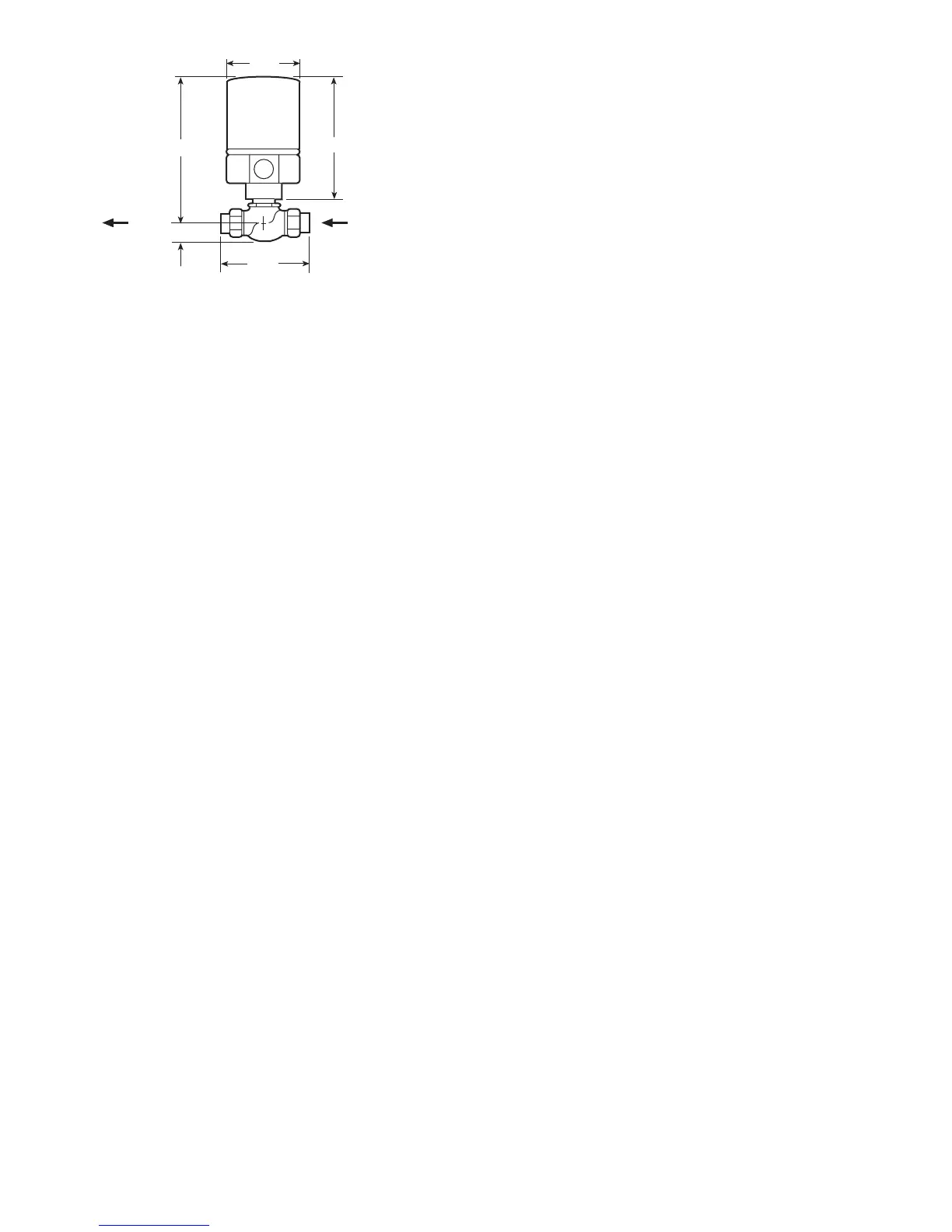
*9-25/32
6-3/4
4-1/4
3-1/4
1-5/16
FLOW
IN ‘A’
OUT
‘AB’
*Includes 2
1
/
32
-in. (52 mm) for linkage extension.
NOTES:
1. Allow 3 in. clearance above actuator for removal. Mount actua-
tors above the valve body at 45-degrees from vertical. Refer to
Fig. 32.
2. Dimensions are in inches.
Fig. 35 — Valve Dimensions