64
3
2
1
8
7
6
5
4
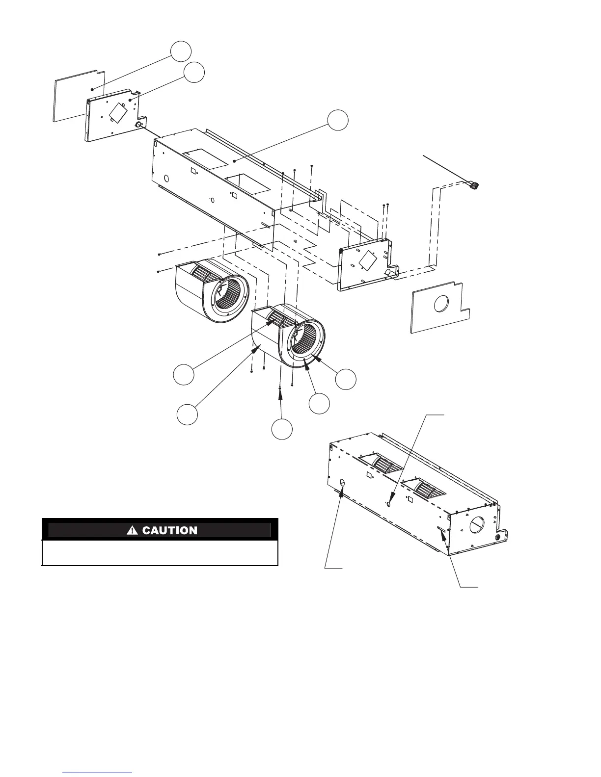
DISCHARGE AIR
TEMPERATURE
SENSOR (OPTIONAL)
OPENING
MOTOR AND
COUPLING
SETSCREW
ACCESS
RETURN AIR
TEMPERATURE
SENSOR (OPTIONAL)
OPENING
MANUAL RESET
HIGH TEMPERATURE
LIMIT SWITCH
(SEE NOTES 2,3)
(SEE CAUTION)
AUTOMATIC RESET
HIGH TEMPERATURE
LIMIT SWITCH
(SEE NOTES 2,3)
(SEE CAUTION)
Fig. 44 — 40UV,UH Ventilator Blower Section Assembly Sheet Metal (All Units)
NOTES:
1. Not all components shown for clarity.
2. Supplied on electric heat units only.
3. Secure capillary tubes to blower housing using high temperature
cable tie. Capillary tube lengths will vary depending on unit size.
t
DO NOT CHANGE LIMIT SWITCH CAPILLARY TUBE LOCA-
TION! LIMIT SWITCHES MAY NOT FUNCTION PROPERLY.
 Loading...


