71
Main Burner
Main burners are factory set and should require no adjustment.
To check ignition of main burners and heating controls, move
thermostat setpoint above room temperature and verify that the
burners light and evaporator fan is energized. Check heating ef-
fect, then lower the thermostat setting below the room temperature
and verify that the burners and evaporator fan turn off.
When replacing unit orifices, order the necessary parts through
RCD. See the High Altitude Gas Conversion Kit Gas Heat-
ing/Electric Cooling 3-15 Ton Small Rooftop Units Accessory LP
(Liquid Propane) Installation Instructions for details.
Heating
1. Purge gas supply line of air by opening union ahead of the
gas valve. If gas odor is detected, tighten union and wait
5 minutes before proceeding.
2. Turn on electrical supply and manual gas valve.
3. Set system switch selector at HEAT position and fan
switch at AUTO or ON position. Set heating temperature
lever above room temperature.
4. The induced-draft motor will start.
5. After a call for heating, the main burners should light
within 5 seconds. If the burner does not light, then there is
a 22-second delay before another 5-second try. If the
burner still does not light, the time delay is repeated. If the
burner does not light within 15 minutes, there is a lockout.
To reset the control, break the 24 v power to W1.
6. The evaporator-fan motor will turn on 45 seconds after
burner ignition.
7. The evaporator-fan motor will turn off in 45 seconds after
the thermostat temperature is satisfied.
8. Adjust airflow to obtain a temperature rise within the
range specified on the unit nameplate.
NOTE: The default value for the evaporator-fan motor on/off de-
lay is 45 seconds. The Integrated Gas Unit Controller (IGC)
modifies this value when abnormal limit switch cycles occur.
Based upon unit operating conditions, the on delay can be re-
duced to 0 seconds and the off delay can be extended to 180 sec-
onds. When one flash of the LED is observed, the evaporator-fan
on/off delay has been modified.
If the limit switch trips at the start of the heating cycle during the
evaporator on delay, the time period of the on delay for the next
cycle will be 5 seconds less than the time at which the switch
tripped. (Example: If the limit switch trips at 30 seconds, the evap-
orator-fan on delay for the next cycle will occur at 25 seconds.) To
prevent short-cycling, a 5-second reduction will only occur if a
minimum of 10 minutes has elapsed since the last call for heating.
The evaporator-fan off delay can also be modified. Once the call
for heating has ended, there is a 10-minute period during which
the modification can occur. If the limit switch trips during this
period, the evaporator-fan off delay will increase by 15 seconds.
A maximum of 9 trips can occur, extending the evaporator-fan
off delay to 180 seconds.
To restore the original default value, reset the power to the unit.
To shut off unit, set system selector switch at OFF position.
Resetting heating selector lever below room temperature will
temporarily shut unit off until space temperature falls below
thermostat setting.
Ventilation (Continuous Fan)
Set fan and system selector switches at ON and OFF positions, re-
spectively. Evaporator fan operates continuously to provide con-
stant air circulation. When the evaporator-fan selector switch is
turned to the OFF position, there is a 30-second delay before the
fan turns off.
FASTENER TORQUE VALUES
START-UP, SYSTEMVU CONTROLS
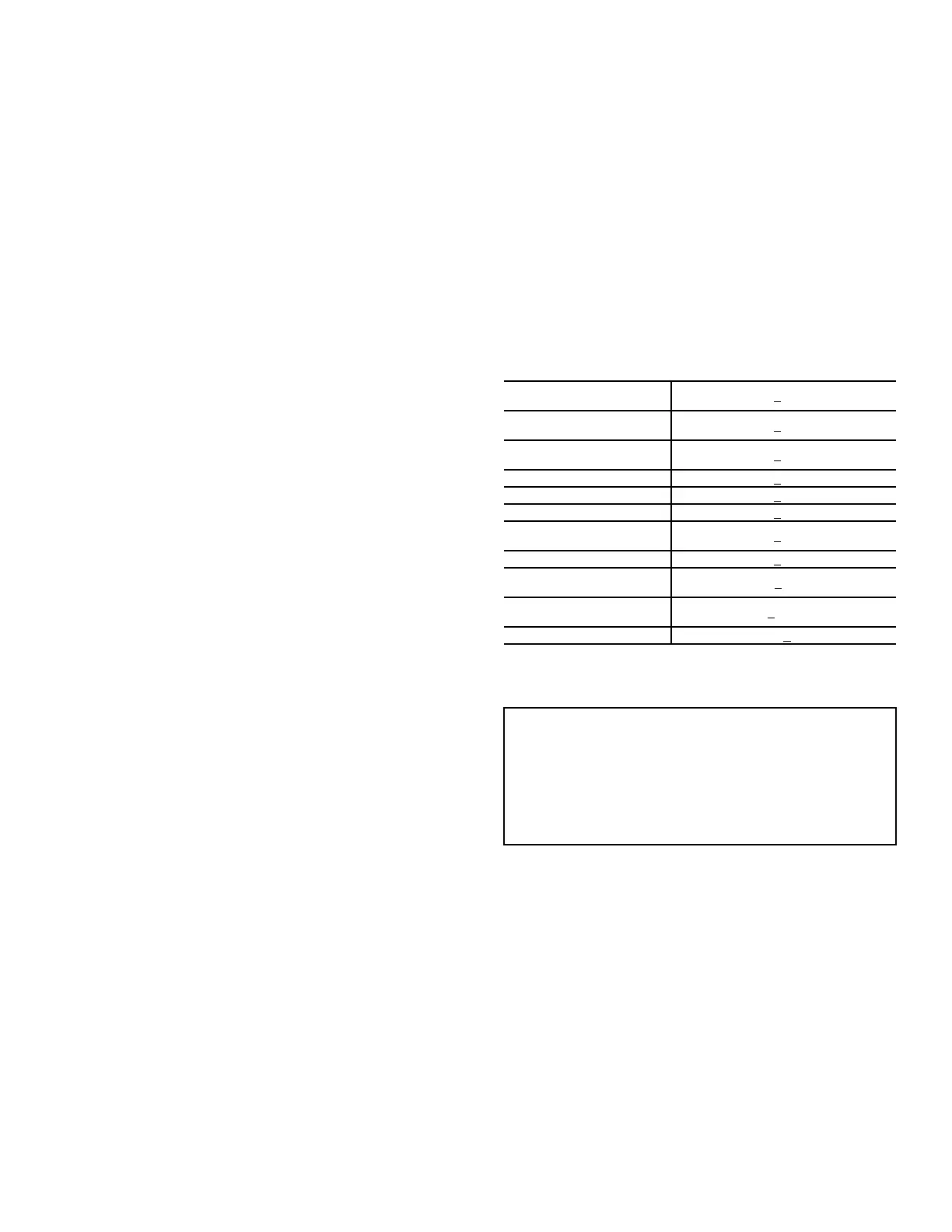
Table 23 — Torque Values
Stator Motor Mounting
Screws
50 in.-lb (5.7 Nm) +
5 in.-lb (0.6 Nm)
Fan Rotor Mounting
Screws (2.4 HP)
50 in.-lb (5.7 Nm) +
5 in.-lb (0.6 Nm)
Fan Rotor Mounting
Screws (3 and 5 HP)
30 in.-lb (3.4 Nm) +
2 in.-lb (0.2 Nm)
Fan Deck Bracket Screws 50 in.-lb (5.7 Nm) + 5 in.-lb (0.6 Nm)
Fan Casing Screws 10 in.-lb (1.1 Nm) +
1 in.-lb (0.1 Nm)
Heat Shield Screws 30 in.-lb (3.4 Nm) +
2 in.-lb (0.2 Nm)
Condenser Motor
Mounting Screws
30 in.-lb (3.4 Nm) +
2 in.-lb (0.2 Nm)
Condenser Hub Set Screw 84 in.-lb (9.5 Nm) + 12 in.-lb (1.5 Nm)
Compressor Mounting
Bolts
12 ft-lb (16.2 Nm) +
2 ft-lb (2.7 Nm)
Tandem Rail Mounting
Bolts
8 ft-lb (10.8 Nm) +
0.5 ft-lb (0.6 Nm)
Crankcase Heater 22.5 in.-lb (2.5 Nm) + 2.5 in.-lb (0.3 Nm)
IMPORTANT: SET-UP INSTRUCTIONS
Installation, wiring and troubleshooting information for the
SystemVu™ Controller: “48/50FC 04-30, 48/50GC 04-06
Single Package Rooftop Units with SystemVu Controls
Version X.X Controls, Start-up, Operation and
Troubleshooting.” Have a copy of this manual available at
unit start-up.

 Loading...


