43
GAS VALVE
All three-phase models are equipped with 2-stage gas valves.
See Fig. 62 for locations of adjustment screws and features on
the gas valve.
To adjust gas valve pressure settings:
CHECK UNIT OPERATION AND MAKE NECESSARY
ADJUSTMENTS
NOTE: Gas supply pressure at gas valve inlet must be within
specified ranges for fuel type and unit size. For natural gas see
Tables 6 and 7. For liquid propane see Tables 8 and 9.
1. Slide out the burner partition panel.
2. Remove manifold pressure tap plug from manifold and
connect pressure gauge or manometer. (See Fig. 59.)
3. Turn on electrical supply.
4. Turn on unit main gas valve.
5. Set room thermostat to call for heat. If unit has two-stage
gas valve, verify high-stage heat operation before attempt-
ing to adjust manifold pressure.
6. When main burners ignite, check all fittings, manifold,
and orifices for leaks.
7. Adjust high-stage pressure to specified setting by turning
the plastic adjustment screw clockwise to increase pres-
sure, counter-clockwise to decrease pressure.
8. For two-stage gas valves, set room thermostat to call for low-
stage heat. Adjust low-stage pressure to specified setting.
9. Replace regulator cover screw(s) when finished.
10. Observe unit heating operation in both high stage and low
stage operation if so equipped. Observe burner flames to
see if they are blue in appearance, and that the flames are
approximately the same for each burner.
11. Turn off unit, remove pressure manometer and replace the
manifold pressure tap plug. (See Fig. 59.)
LIMIT SWITCH
Remove the indoor blower access panel. Limit switch is located
on the heat exchanger cover panel. See Fig. 58.
Burner Ignition
Unit is equipped with a direct spark ignition 100% lockout sys-
tem. The Integrated Gas Unit Controller (IGC) is located in the
control box (see Fig. 60). The IGC contains a self-diagnostic
LED (light-emitting diode). A single LED (see Fig. 63) on the
IGC provides a visual display of operational or sequential prob-
lems when the power supply is uninterrupted. When a break in
power occurs, the IGC will be reset (resulting in a loss of fault
history) and the indoor (evaporator) fan ON/OFF times will be
reset. The LED error code can be observed through the viewport.
During servicing, refer to the label on the control box cover or
Table 10 for an explanation of LED error code descriptions.
If lockout occurs, unit may be reset by interrupting power supply
to unit for at least 5 seconds.
Orifice Replacement
This unit uses orifice type LH32RFnnn (where “nnn” indicates
orifice reference size). When replacing unit orifices, order the
necessary parts through RCD. See the High Altitude Gas Con-
version Kit Gas Heating/Electric Cooling 3-15 Ton Small Roof-
top Units Accessory LP (Liquid Propane) Installation Instruc-
tions for details.
Ensure each replacement orifice is tight as its threads into the
manifold pipe and the orifice projection does not exceed maxi-
mum value. See Fig. 57.
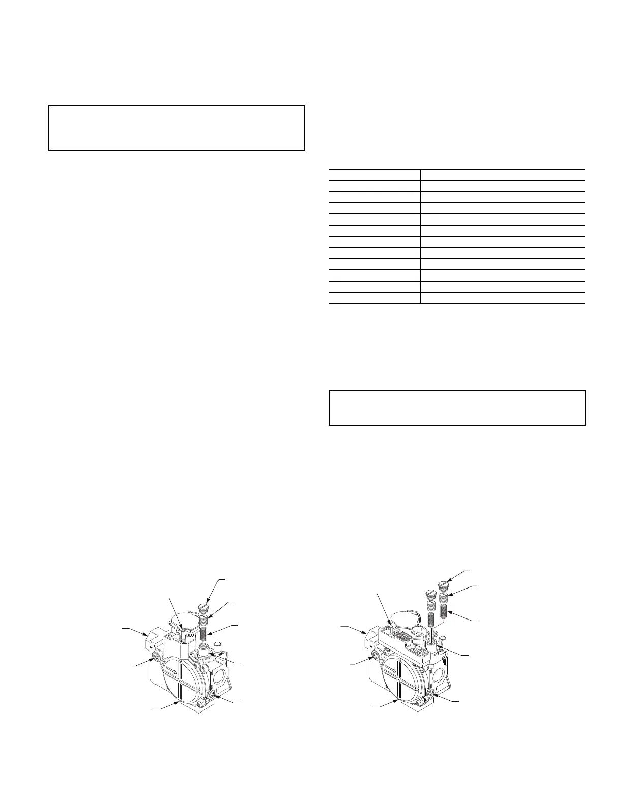
Fig. 62 — Typical Gas Valves
IMPORTANT: Leak check all gas connections including the
main service connection, gas valve, gas spuds, and manifold
pipe plug. All leaks must be repaired before firing unit.
Table 10 — LED Error Code Descriptions
a
a. A 3-second pause exists between LED error code flashes. If more than one er-
ror code exists, all applicable codes will be displayed in numerical sequence.
LED INDICATION ERROR CODE DESCRIPTION
ON Normal Operation
OFF Hardware Failure
1 Flash
b
b. Indicates a code that is not an error. The unit will continue to operate when this
code is displayed.
Evaporator Fan On/Off Delay Modified
2 Flashes Limit Switch Fault
3 Flashes Flame Sense Fault
4 Flashes 4 Consecutive Limit Switch Faults
5 Flashes Ignition Lockout Fault
6 Flashes Induced-Draft Motor Fault
7 Flashes Rollout Switch Fault
8 Flashes Internal Control Fault
9 Flashes Software Lockout
LEGEND
LED — Light Emitting Diode
IMPORTANT: Refer to Tables 11 and 12 for additional
troubleshooting information.
Plastic Adjust
Screw
Regulator Spring
(Propane — White
Natural — Silver)
Gas Pressure
Regulator
Adjustment
Manifold
Pressure Tap
NPT Outlet
Inlet
Pressure
Tap
On/Off
Switch
Regulator
Cover Screw
NPT Inlet
Single Stage
Plastic Adjust
Screw (2)
Regulator Spring (2)
(Propane — White
Natural — Silver)
Low Stage
Gas Pressure
Regulator
Adjustment
Manifold
Pressure Tap
NPT Outlet
Inlet
Pressure
Tap
On/Off
Switch
Regulator
Cover Screw (2)
NPT Inlet
2 Stage

 Loading...


