41
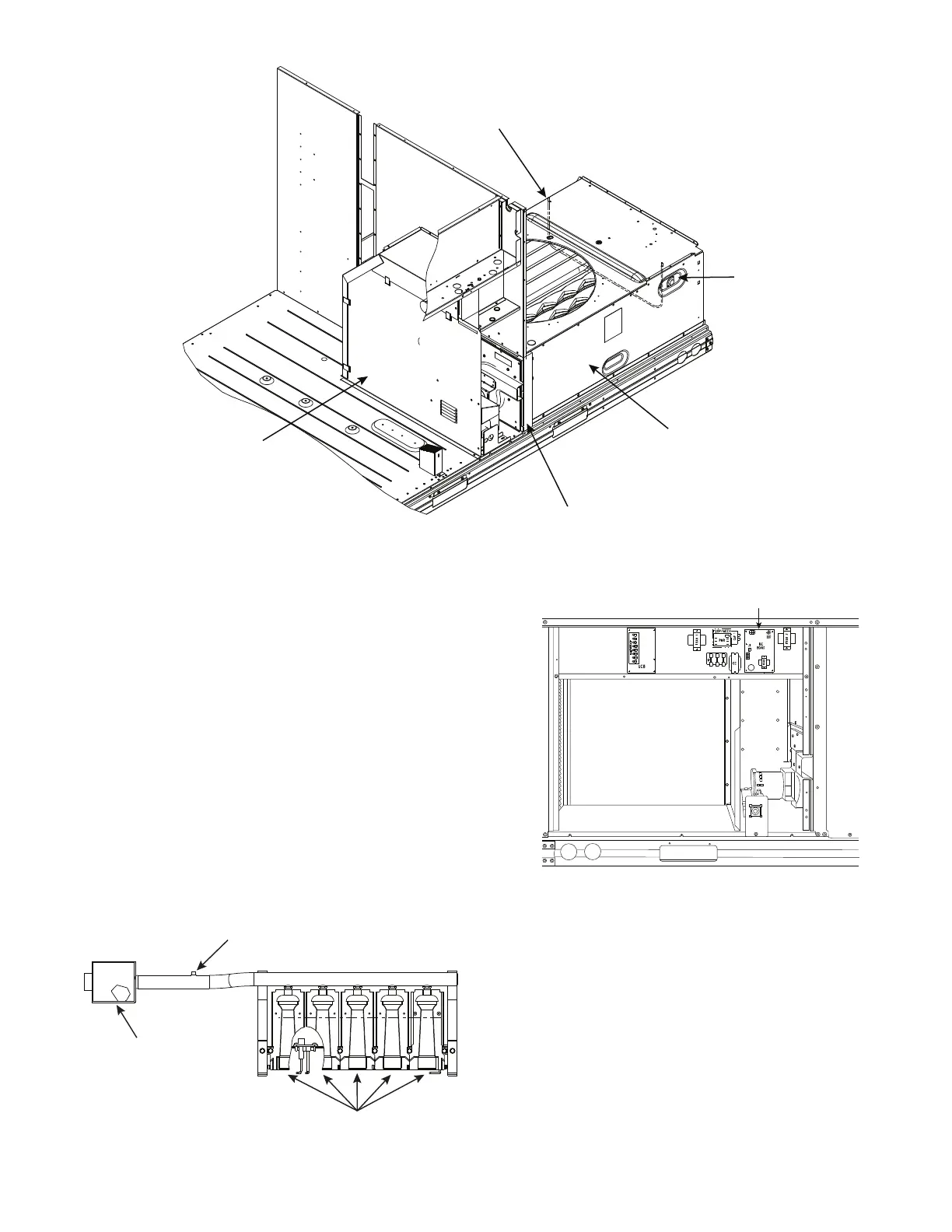
Fig. 58 — Heat Exchanger Access - Internal Panels, Center Post and HX Rack Locations
CLEANING AND ADJUSTMENT
1. Remove burner rack from unit as described in “Removal
and Replacement of Gas Train” section.
2. Inspect burners; if dirty, remove burners from rack. (Mark
each burner to identify its position before removing from
the rack.)
3. Use a soft brush to clean burners and cross-over port as
required.
4. Adjust spark gap. (See Fig. 61.)
5. If factory orifice has been removed, check that each orifice
is tight at its threads into the manifold pipe and that orifice
projection does not exceed maximum value. See Fig. 57.
6. Reinstall burners on rack in the same locations as factory-
installed. (The outside crossover flame regions of the out-
ermost burners are pinched off to prevent excessive gas
flow from the side of the burner assembly. If the pinched
crossovers are installed between two burners, the flame
will not ignite properly.)
7. Reinstall burner rack as described in “Removal and
Replacement of Gas Train” section.
Fig. 59 — Burner Tray Details
Fig. 60 — Unit Control Box/IGC Location
REMOVING THE HEAT EXCHANGER
The following procedure details the steps to remove the heat ex-
changed from the unit.
1. Turn off electric power to the unit and shut off the unit’s
gas supply.
2. Remove the two exterior panels: control box access panel
and indoor blower access panel.
3. Remove the unit center post (see Fig. 58).
4. Disconnect the two wires from the gas limit switch.
5. Remove the three interior panels: control box high voltage
panel, burner partition panel, and heat exchanger cover panel.
6. Disconnect the wires connected to the gas valve. Mark
each wire.
7. Disconnect the igniter wires and sensor wires at the inte-
grated gas controller (IGC).
Heat Exchanger
Cover Panel
Gas Limit Switch
Unit Center Post
Burner Partition Panel
Heat Exchanger
Support Rack
Burners
Gas Valve
Manifold Pressure Tap
Integrated Gas
Controller (IGC)

 Loading...


