27
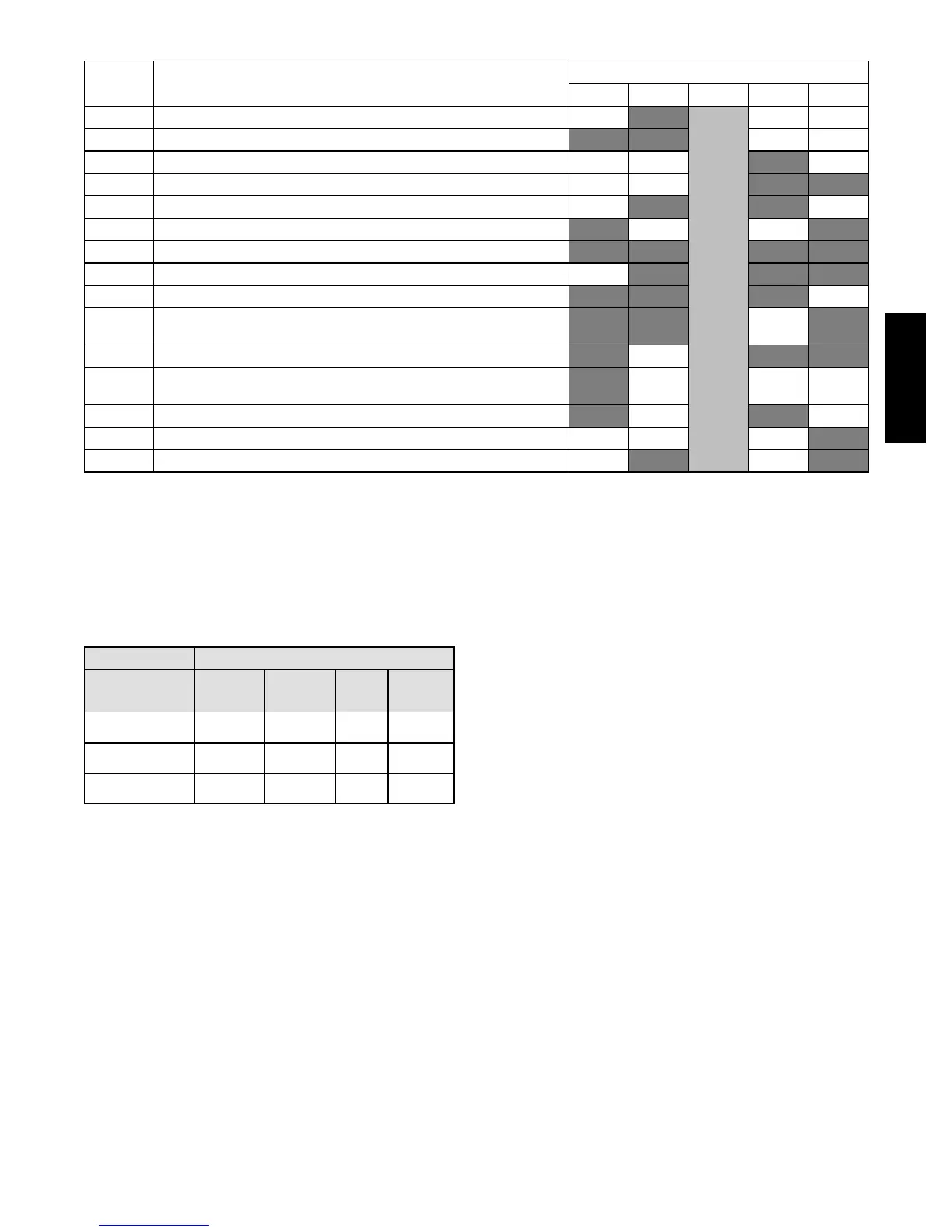
Table 4 – Status Code Descriptions for ISC Board LEDs
ERROR# ERROR NAME
LED INDICATION
LED01 LED02 LED03 LED04 LED05
1 Check Smoke Detector/PMR/AUX RED
Blinking
Green
LED
(Note 1)
2 Check HPS/LPS/COFS RED RED
3 Call for Y3 with no call for Y1. Check Y1 wiring. RED
4 Call for Y3 with no call for Y1/Y2. Check Y1 wiring. RED RED
5 Call for Y2 with no call for Y1. Check Y1 wiring. RED RED
6 Call for W2 with no call for W1. Check W1 wiring. RED RED
7 Call for heat (W1/W2) and cooling (Y1/Y2/Y3). Check thermostat wiring. RED RED RED RED
8 Call for heat (W1/W2) with no IFM. Check G wiring. RED RED RED
9 Call for cooling (Y1/Y2/Y3) with no G. Check G wiring RED RED RED
10
Call for heat (W1/W2) and cooling (Y1/Y2/Y3) with no G.
Check thermostat and G wiring.
RED RED RED
11 C heck ISC Board and the thermostat wiring RED RED RED
12
Call for Economizer Y1 Feedback (ECON) from economizer with no call
for Y1 from thermostat. Check thermostat and economizer wiring.
RED
13 C heck ISC Board and the thermostat wiring RED RED
14 C heck ISC Board and the thermostat wiring RED
15 C heck ISC Board and the thermostat wiring RED RED
NOTES: 1. Green L E D Blinking at 1HZ indicates normal operation.
2. Solid red LED indicates an error exists, see above LED configuration.
Cooling —
In the Cooling Mode, the small and large compressors will
be sequenced to maintain the thermostat temperature
setpoint. The chart below shows the cooling operation
based on the following conditions.
INPUT OUTPUT
Thermostat
Comp re sso r
C1
Comp re sso r
C2
Indoor
Fan
Speed
Outdoor
Fan
Speed
First Stage Cooling
(Y1)
On Off Low
Low
(700 rpm)
Second Stage Cooling
(Y2)
Off On Medium
Medium
(800 rpm)
Third Stage Cooling
(Y3)
On On High
High
(1000 rpm )
The outdoor fan and VFD controlled indoor--fan will
operate at low, medium and high speed. The indoor--fan
speed (rpm) is factory set by the CFM and static pressure
requirements for the unit installed.
Economizer (Optional) —
When the Economizer is in Free Cooling Mode and a
demand for cooling exist (Y1 on the thermostat), the
Economizer will modulate the outdoor--air damper to
provide a 50_F(10_C) to 55_F(13_C) mixed--air
temperature into the zone and run the indoor--fan at high
speed. As mixed--air temperature fluctuates above 55 ºF
(13_C) or below 50_F(10_C) dampers will be modulated
(open or close) to bring the mixed--air temperature back
within control. Upon more call for cooling (Y2 on the
thermostat), the outdoor--air damper will maintain its
current position, compressor C1 will run and the
outdoor--fan will run at low speed. If there is further
demand for cooling, the outdoor--air damper will maintain
its current position, only compressor C2 will run and the
outdoor--fan will run at medium speed. The VFD
controlled indoor--fan will operate at high speed
regardless of the cooling demand.
If the increase in cooling capacity causes the mixed--air
temperature to drop below 45_F(7_C), the outdoor--air
damper will return to the minimum position. If the
mixed--air temperature continues to fall, the outdoor--air
damper will close. Control returns to normal once the
mixed--air temperature rises above 48_F(9_C). The
power exhaust fans will be energized and de--energized, if
installed, as the outdoor--air damper opens and closes.
In field--installed accessory CO
2
sensors are connected to
the Economizer, a demand controlled ventilation strategy
will begin to operate. As the CO
2
level in the zone
increases above the CO
2
set--point, the minimum position
of the damper will be increased proportionally. As the
CO
2
level decreases because of the increase of fresh air,
the outdoor--air damper will be proportionally closed. For
economizer operation, there must be a thermostat call for
the fan (G). If the unit is occupied and the fan is on, the
damper will operate at minimum position. Otherwise, the
damper will be closed.
Low Ambient Cooling Operation down to 40_F(4_C) —
In Low Ambient RTU conditions when the temperature is
between 55_F(13_C) and 40_F(4_C), the Low Ambient
Switch (LAS) will be active and the outdoor--fans will run to
the pre--set factory outdoor--fan speed. When the temperature
is greater than 65_F(18_C), the Low Ambient Switch will
deactivate and the outdoor--fans will run in the standard
cooling mode. If the Outdoor Fan Select Switch (see Fig.
41) is in the up position, the outdoor fans will run in the Fan
Cycle Speed Mode (FCS) set to 250 rpm. If the Outdoor Fan
48HC48LC
 Loading...

