35
Connections and Applications
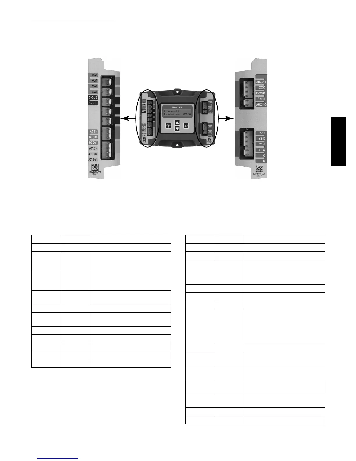
W7220 Economizer Module Wiring —
Use Fig. 44 and Tables 7 and 8 to locate the wiring
terminals for the Economizer module.
W7220 Controller
Left Terminal
Block Label
Right Terminal
Block Label
C12014
Fig. 44 -- W7220 Economizer Module Terminal Connection Labels
Table 7 – Economizer Module --
Left Hand Terminal Blocks
Label Type Description
Top Left Terminal Block
MAT
MAT
20k NTC
and
COM
Supply Air Temperature Sensor
(polarity insensitive connection)
OAT
OAT
20k NTC
and
COM
Outdoor Air Temperature Sensor
(polarity insensitive connection)
S --- B U S
S --- B U S
S --- B u s
(Sylk Bus)
Enthalpy Control Sensor
(polarity insensitive connection)
Bottom Left Terminal Block
I A Q 2 --- 1 0 2 --- 1 0 V d c Air Quality Sensor Input
(e.g. CO
2
sensor)
IAQ COM COM Air Quality Sensor Common
IAQ 24V 24 Vac Air Quality Sensor 24 Vac Source
A C T 2 --- 1 0 2 --- 1 0 V d c Damper Actuator Output (2--- 10 Vdc)
ACT COM COM Damper Actuator Output Common
ACT 24V 24 Vac Damper Actuator 24 Vac Source
Table 8 – Economizer Module --
Right Hand Terminal Blocks
Label Type Description
Top R i ght Te r min a l B lock
n/a The first terminal is not used
AUX2 I 24 Vac IN Input from T hermostat W1 indicating
base unit is in Heat mode, damper
controls to High Fan Speed
setpoints
OCC 24 Vac IN Occupied / Unoccupied Input
E --- G N D E --- G N D Earth Ground --- System Required
EXH1 24 Vac OUT Exhaust Fan 1 Output
AUX1 O 24 Vac OUT Programmable:
Exhaust fan 2 output
or
Erv
or
System Alarm output
Bottom Right Terminal Block
Y 2 --- I 24 Vac IN Y2 in --- Cooling Stage 2 Input from
space thermostat
Y 2 --- O 24 Vac OUT Y2 out --- Cooling Stage 2 Output to
stage 2 mechanical cooling
Y 1 --- I 24 Vac IN Y1 in --- Cooling Stage 2 Input from
space thermostat
Y 1 --- O 24 Vac OUT Y1 out --- Cooling Stage 2 Output to
stage 2 mechanical cooling
C COM 24 Vac Common
R 24 Vac 24 Vac Power (Hot)
Refer to Figs 45 and 46 for sensor and controls connections.
48HC48LC
 Loading...

