52
Navigation Keys and Status LEDs: The Navigation keys
and Status LEDs are detailed in the following table.
Alarm
Warn.
On
Com.
OK
B
a
c
k
3
4
1
2
5
6
5
7
C13114
1 Com. LED: Flashes when bus communications is
communicating.
2 Green LED/On: Control selection is working.
3 Yellow LED/Warn.: Indicates a warning.
4 Flashing Red LED/Alarm: Indicates an alarm.
5 Arrows YB: Use the Up and Down arrow keys
to navigate between parameter groups, parameters
and within parameters. Also used for setting local
reference.
6 Back key: Press to move to the previous step or
layer in the navigation structure.
7 OK key: Press to select the currently displayed
parameter and for accepting changes to parameter
settings.
Operation Keys and LEDs: The following table details the
functions of the Operating keys. An illuminated yellow LED
above the key indicates the active key.
O
Reset
Hand
On
Auto
On
1 2 3
C13115
1 Hand On key: Starts the motor and enables
control of the variable frequency drive (VFD) via
the VFD Keypad option.
NOTE: Please note that terminal 27 Digital
Input (5--12 Terminal 27 Digital Input) has coast
inverse as default setting. This means that the
Hand On key will not start the motor if there is no
24V to terminal 27, so be sure to connect terminal
12 to terminal 27.
2 Off/Reset key: Stops the motor (off). If in alarm
mode the alarm will be reset.
3 Auto On key: The variable frequency drive is
controlled either via control terminals or serial
communication.
Connecting the Keypad to the VFD
The VFD keypad can be mounted directly to the variable
frequency drive, provided you can easily access the front
panel of the VFD. If you don’t have easy access to the
VFD front panel, use the cable included with the kit to
connect the keypad to the VFD.
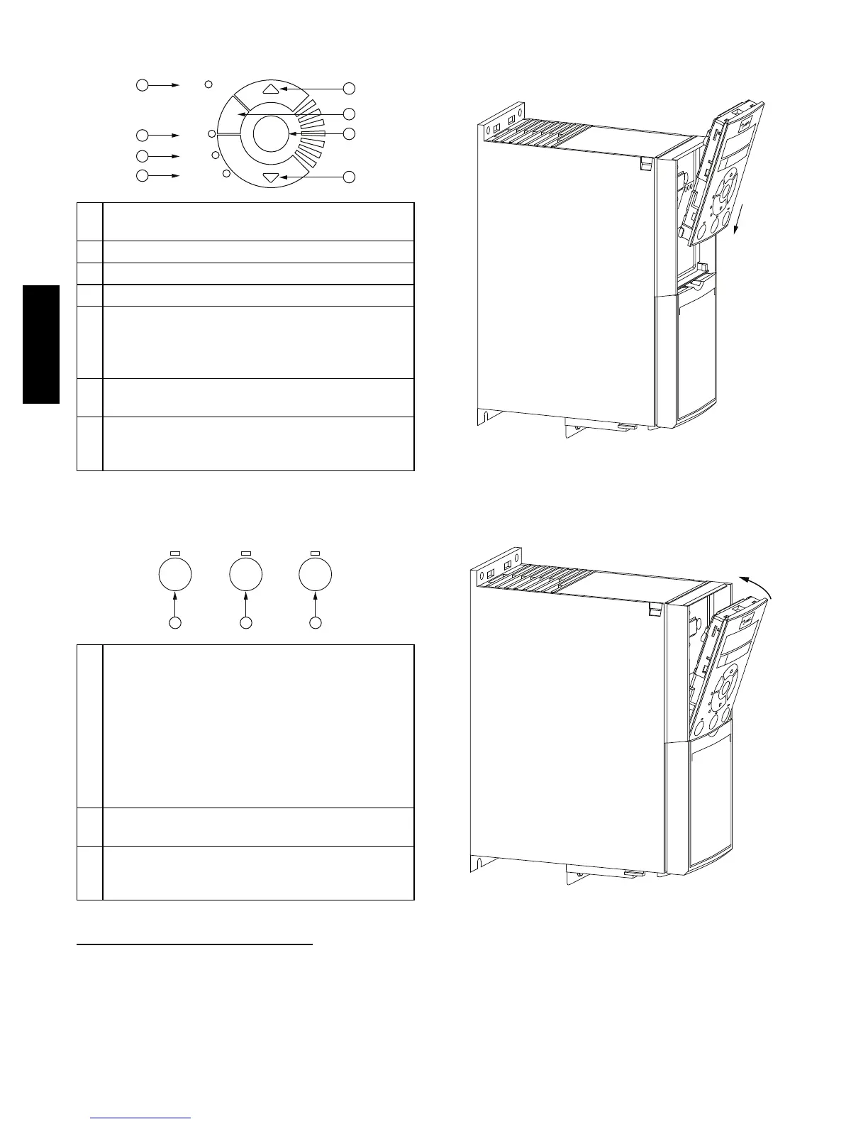
Connecting the Keypad Directly to the VFD —
1. Place the bottom of the VFD keypad into the variable
frequency drive as shown in Fig. 56.
C13116
Fig. 56 -- Align Bottom of VFD Keypad with Opening
in VFD Front Panel
2. Push the top of the VFD keypad into the variable fre-
quency drive as shown in Fig. 57.
C13117
Fig. 57 -- Secure Keypad in Place
Using the Cable to Connect the Keypad to the VFD —
The VFD keypad can be connected to the variable
frequency drive via the cable included with the
Multi--Speed VFD display kit (PN: CRDISKIT002A00).
48HC48LC
 Loading...

