EasyManua.ls Logo

Carrier 50TC-D25 User Manual

Carrier 50TC-D25
82 pages
To Next Page IconTo Next Page
Page #1 background imageLoading...
Page #1 background image
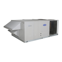
50TC*17- 30
Nominal 15 to 27.5 Tons
With Puron ® (R-410A) Refrigerant
Service and Maintenance Instructions
TABLE OF CONTENTS
TABLE OF CONTENTS 1.........................
SAFETY CONSIDERATIONS 1....................
UNIT ARRANGEMENT AND ACCESS 3...........
SUPPLY FAN (BLOWER) SECTION 4..............
STAGED AIR VOLUME (SAV) CONTROL: 2SPEED
FAN WITH VARIABLE FREQUENCY DRIVE (VFD) 6
ADDITIONAL VFD INSTALLATION AND
TROUBLESHOOTING 7..........................
CONDENSER COIL SERVICE 8...................
EVAPORATOR COILS 10.........................
HIMIDIMIZER DEHUMIDIFICATION SYSTEM 12
THERMOSTATIC EXPANSION VALVE (TXV) 17....
PURON (R410A) REFRIGERANT 19.............
COOLING CHARGING CHARTS 20................
COMPRESSORS 24..............................
TROUBLESHOOTING THE COOLING SYSTEM 26..
CONVENIENCE OUTLETS 27....................
SMOKE DETECTORS 28.........................
INDICATORS 34................................
PROTECTIVE DEVICES 35.......................
PREMIERLINK CONTROL 36...................
RTUOPEN CONTROL SYSTEM 38................
ECONOMI$ER SYSTEMS 40......................
PRESTARTUP/STARTUP 49....................
STARTUP, PREMIERLINK CONTROLS 50.......
STARTUP, RTUOPEN CONTROLS 51............
FASTENER TORQUE VALUES 51.................
APPENDIX I. MODEL NO. NOMENCLATURE 52...
APPENDIX II. PHYSICAL DATA 53................
APPENDIX III. FAN PERFORMANCE 61...........
APPENDIX IV. WIRING DIAGRAMS 67............
APPENDIX V. MOTORMASTER SENSOR
LOCATIONS 80.................................
UNIT START-UP CHECKLIST 81..................
SAFETY CONSIDERATIONS
Installation and servicing of air-conditioning equipment
can be hazardous due to system pressure and electrical
components. Only trained and qualified service personnel
should install, repair, or service air-conditioning
equipment. Untrained personnel can perform the basic
maintenance functions of replacing filters. Trained service
personnel should perform all other operations.
When working on air-conditioning equipment, observe
precautions in the literature, tags and labels attached to
the unit, and other safety precautions that may apply.
Follow all safety codes. Wear safety glasses and work
gloves. Use quenching cloth for unbrazing operations.
Have fire extinguishers available for all brazing
operations.
Follow all safety codes. Consult local building codes and
National Electrical Code (NEC) for special requirements.
Recognize safety information. This is the safetyalert
symbol . When you see this symbol on the unit and in
instructions or manuals, be aware of the potential for
physical injury hazards.
Understand the signal words DANGER, WARNING, and
CAUTION. These words are used with the safetyalert
symbol. DANGER identifies a hazardous situation which,
if not avoided, will result in death or severe personal
injury. WARNING indicates a hazardous situation which,
if not avoided, could result in death or personal injury.
CAUTION indicates a hazardous situation which, if not
avoided, could result in minor to moderate injury or
product and property damage. NOTICE is used to address
practices not related to physical injury. NOTE is used to
highlight suggestions which will result in enhanced
installation, reliability, or operation.
Question and Answer IconNeed help?

Do you have a question about the Carrier 50TC-D25 and is the answer not in the manual?

Carrier 50TC-D25 Specifications

General IconGeneral
TypeSplit System
RefrigerantR-410A
Operating Voltage208/230V
Phase1
Sound Level (Outdoor)72 dB(A)

Summary

Safety Considerations

General Safety Guidelines

Discusses hazards, safety codes, signal words (DANGER, WARNING, CAUTION, NOTICE).

Specific Hazard Warnings

Details various hazards like cut, damage, fire, electrical shock, and operational safety.

Staged Air Volume (SAV) Control: 2-Speed Fan with Variable Frequency Drive (VFD)

SAV Indoor Fan Speed System

Explains how the SAV system uses VFD to adjust fan speed for different operating modes.

Additional VFD Installation and Troubleshooting

Humidi-Mizer® Adaptive Dehumidification System

Humidi-MiZer® Modes Overview

Introduces the system's capability for multiple humidity control modes.

Refrigerant Flow Schematics

Provides diagrams illustrating refrigerant flow in Normal, Subcooling (Reheat 1), and Hot Gas Reheat (Reheat 2) modes.

Humidi-MiZer® Troubleshooting

Provides a table of common problems, causes, and remedies for the Humidi-MiZer system.

Thermostatic Expansion Valve (TXV)

TXV Replacement Procedure

Step-by-step instructions for replacing the TXV, including safety precautions and refrigerant handling.

Puron® (R-410A) Refrigerant

Refrigerant Charge Preparation

Outlines steps for preparing the unit for refrigerant charge adjustment.

Cooling Charging Charts

Provides graphical charts for determining correct refrigerant charge based on suction temperature and pressure.

Compressors

Compressor Unit Damage Hazard

Warns about POE oil's hygroscopic nature and avoiding atmospheric exposure.

Troubleshooting the Cooling System

Cooling Service Troubleshooting Table

A table listing common cooling system problems, their causes, and recommended remedies.

Convenience Outlets

Electrical Operation Hazard

Warns about electrical hazards related to convenience outlets and the need for lockout/tagout.

Smoke Detectors

FIOP Smoke Detector Wiring and Response

Details the wiring and response logic for FIOP smoke detectors, including PremierLink and RTU-Open integration.

Typical Smoke Detector System Wiring

Provides a diagram illustrating the wiring for the smoke detector system.

Sensor and Controller Tests

Procedures for testing sensor and controller alarm/trouble states and dirty status.

Protective Devices

Compressor Protection

Details compressor protection mechanisms like overcurrent, overtemperature, and high-pressure switch.

Low Pressure Switch

Explains the function of the low-pressure switch for charge loss protection.

Troubleshooting Controller's Trouble LED

Guides on diagnosing issues when the controller's Trouble LED is on or flashing.

Troubleshooting Sensor's Trouble LED

Steps for diagnosing issues when a sensor's Trouble LED is on.

Troubleshooting Sensor's Power LED

Steps for diagnosing issues when a sensor's Power LED is off.

Troubleshooting Controller's Power LED

Steps for diagnosing issues when a controller's Power LED is off.

Troubleshooting Remote Test/Reset Station

Guides on issues with remote test/reset station trouble LED.

Supply Fan Motor Protection

Details motor protection devices like internal protection and external overload breakers.

Troubleshooting Supply Fan Motor Overload Trips

Explains common causes for supply fan motor overload trips.

PremierLink™ Control

PremierLink Control Overview

Introduces the PremierLink controller and its sensors.

PremierLink Controller Description

Details the PremierLink controller's compatibility, mounting, and included sensors.

RTU-Open Control System

RTU Open Controller Functionality

Explains the controller's integrated application programming for performance and efficiency.

Electrical Shock Hazard Warning

Warns of electrical hazards during RTU-OPEN controller wiring.

Additional RTU-OPEN Installation and Troubleshooting

Refers to specific manuals for detailed installation and troubleshooting information.

RTU-OPEN Control Module Diagram

Provides a detailed diagram of the RTU-OPEN control module with terminal connections.

Economiser Systems

EconoMi$er IV Input/Output Logic

A table summarizing the input/output logic for the EconoMi$er IV system.

EconoMi$er IV Control Modes

Explains the different control modes available for the EconoMi$er IV.

Demand Control Ventilation (DCV)

Discusses DCV criteria, calculation of ventilation rates, and CO2 sensor integration.

Pre-Start-Up/Start-Up

Personal Injury Hazard Warning

General warnings about safety practices, PPE, and refrigerant handling during checks.

Electrical Operation Hazard Warning

Electrical safety warnings regarding grounding and NEC compliance.

Initial Start-Up Inspections

Checks to perform before initial start-up, including shipping damage and installation verification.

Compressor Rotation Check

Details how to check and verify compressor rotation direction.

Cooling Start-Up Procedure

Steps to start the unit in cooling mode, set thermostat, and check charge.

Start-Up, PremierLink™ Controls

Electrical Operation Hazard Warning

Warning about electrical hazards and grounding requirements.

PremierLink Controller Start-Up

Instructions for starting up and configuring the PremierLink controller using Carrier software.

Start-Up, RTU-Open Controls

RTU-OPEN Controller Set-Up

Refers to manuals for RTU-OPEN controller installation, wiring, and troubleshooting.

Appendix IV. Wiring Diagrams

Wiring Diagram Reference Table

A table listing wiring diagram part numbers for different unit sizes and options.

Control Diagram (208/230V, 460V, 575V)

Wiring diagram for STD TIER PAC Control.

Control Diagram (460V, 575V 3 PH)

Wiring diagram for STD TIER PAC Control (460V/575V 3 PH).

Power Diagram (208/230V 3 PH)

Power diagram for 50TC units with Humidi-MiZer.

Power Diagram (460/575V 3 PH)

Power diagram for 50TC units with Humidi-MiZer (460/575V 3 PH).

Power Diagram with Dehumidification (208/230V 3 PH)

Power diagram for 50TC units with Dehumidification.

Power Diagram with Dehumidification (460/575V 3 PH)

Power diagram for 50TC units with Dehumidification (460/575V 3 PH).

Power Diagram (208-230V 3 PH) with Humidi-MiZer

Power diagram for 50TC units with Humidi-MiZer.

Power Diagram (460-3-60) with Humidi-MiZer

Power diagram for 50TC units with Humidi-MiZer (460-3-60).

Power Diagram (575-3-60) with Humidi-MiZer

Power diagram for 50TC units with Humidi-MiZer (575-3-60).

PremierLink™ System Control Wiring Diagram

Wiring diagram for the PremierLink system control.

Unit Start-Up Checklist

Pre-Start-Up Checks

A checklist of pre-start-up inspections required before unit operation.

Start-Up Electrical Checks

Checks for supply voltage, compressor amps, and fan amps.

Start-Up Temperature and Pressure Checks

Measurements for outdoor, return, and supply air temperatures, and system pressures.

Related product manuals