1. Horizontal and Downflow.
Each furnace requires 2 filters which are installed in the
return-air duct. (See Fig. 4 and 5.) To remove filters for
cleaning or replacement, proceed as follows:
a. Turn off electrical supply before removing blower access
door.
b. Remove blower access door.
c. Reach up behind top plate, tilt filters toward center of
return-air plenum, remove filters, and clean as needed.
Replace if torn.
d. Furnaces are equipped with permanent, washable filters.
e. Clean filters by spraying tap water through filter from
opposite direction of airflow.
f. Rinse and let dry. Oiling or coating of filters is not
recommended or required.
g. Reinstall filters.
h. Replace blower access door and turn on electrical supply to
furnace.
2. Upflow.
Each furnace requires 1 or 2 filters which are installed in the
blower compartment. (See Fig. 6.) To remove filters for
cleaning or replacement, proceed as follows:
a. Turn off electrical supply before removing blower and
control access doors.
b. Release filter retainer from clip at front of furnace casing.
(See Fig. 6.) For side return, clips may be used on either or
both sides of the furnace.
c. Slide filter out.
d. Clean filters by spraying tap water through filter from
opposite direction of airflow.
e. Rinse and let dry. Oiling or coating of filter is not
recommended or required.
f. Place filter in furnace.
g. Replace blower and control access doors and turn on
electrical supply to furnace.
BLOWER MOTOR AND WHEEL — For long life, economy, and
high efficiency, clean accumulated dirt and grease from the blower
wheel and motor annually.
The following steps should be performed by a qualified service
technician:
Some motors have prelubricated sealed bearings and require no
lubrication. These motors can be identified by the absence of oil
ports on each end of the motor. For those motors with oil ports,
lubricate as follows:
Fig. 4—Horizontal Filter Arrangement
A82173
FIELD-SUPPLIED
FILTER RETAINERS
AIRFLOW
D
12″
4″
Fig. 5—Downflow Filter Arrangement
A88486
RETURN-AIR
PLENUM
AIRFLOW
ACCESS DOOR
INSTALLATION
POSITION
OF FILTERS
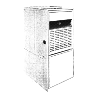
Fig. 6—Model 58TUA Upflow
A93393
DRAFT
SAFEGUARD
SWITCH
PRESSURE
SWITCHES
FILTER
RETAINER
WASHABLE
FILTER
MOUNTING
SCREWS
MAIN
LIMIT
SWITCH
RELIEF
BOX
MANUAL
RESET
LIMIT
SWITCH
CONTROL
3

 Loading...