T-319 2–6
2.1.4 Receiver
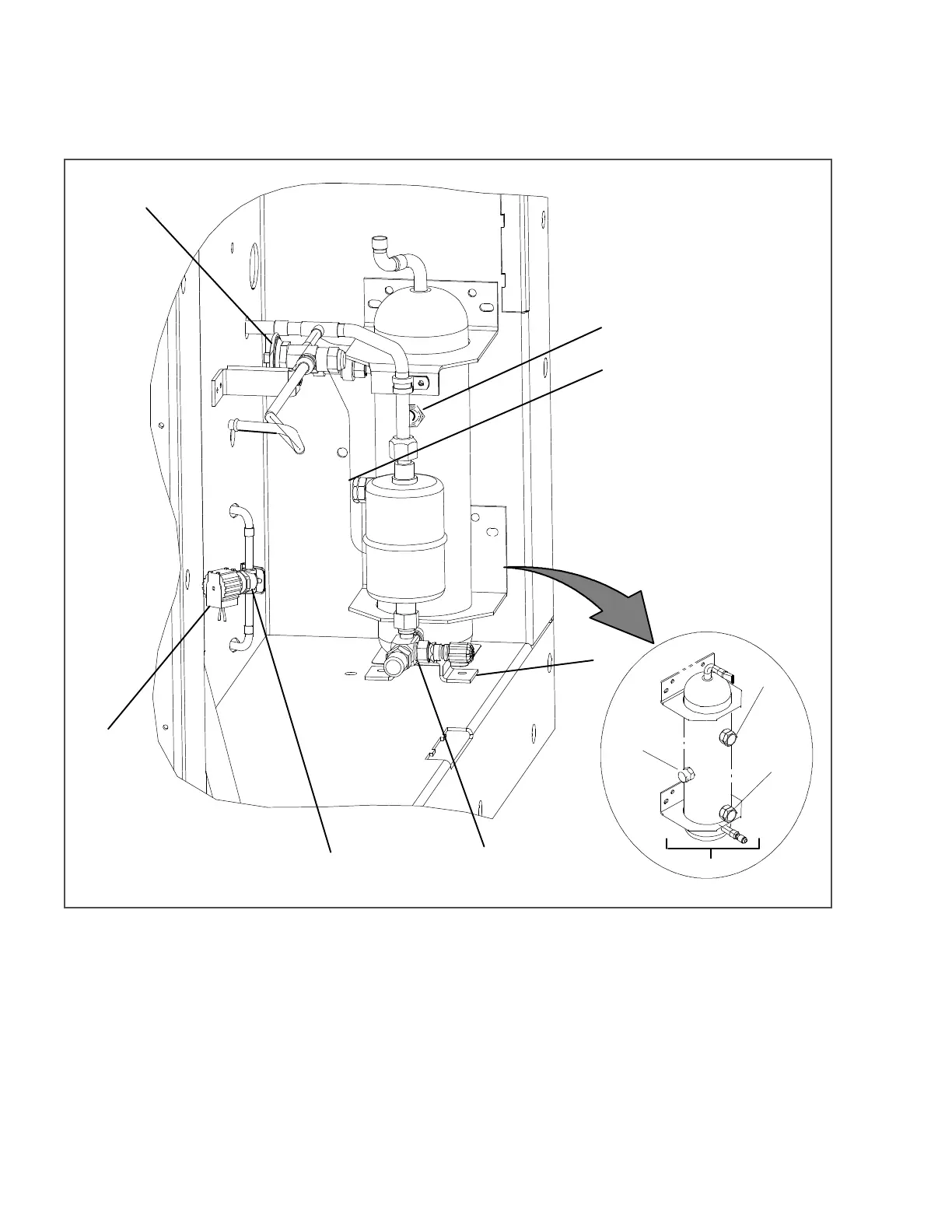
The dual temperature system includes a larger receiver designed to accommodate the additional refrigerant
required for this configuration.
Figure 2.6 Condenser Section
1. Receiver
2. Sight Glass
3. Moisture-Liquid Indicator
4. Fusible Plug OR Rupture Disc
5. Liquid Line Valve Bracket
6. Liquid Line Valve
7. Host Liquid Line Solenoid Valve Body
8. Host Liquid Line Solenoid Valve Coil
9. Quench Valve
- - - - -
2.1.5 Control Box
The dual temperature system includes four additional contactors (PA, PB, VE, VH) and an auxiliary contact as illus-
trated in Figure 2.7.

 Loading...


