2–17 T-319
2.6 SAFETY AND PROTECTIVE DEVICES
Unit components are protected from damage by safety and protective devices listed in the following table. These
devices monitor the unit operating conditions and open a set of electrical contacts when an unsafe condition
occurs.
f. Remote Evaporator
Fan Motor
Full Load Amps 1 amp
g. Evaporator Coil
Heaters
Number of Heaters 6
Rating 750 watts +5/-10% each @ 230VAC
Resistance (cold) 66.8 to 77.2ohms @ 20°C (68°F)
Type Sheath
h. Fuses
Control Circuit 7.5 amps (F3A, F3B)
Controller/DataCORDER 5 amps (F1 & F2)
Emergency Defrost 5 amps (FED)
Drain Line Heater 5 amps (FDH)
Humidity Power
Transformer
5 amps (FH)
i. Compressor Crankcase Heater 180 watts @ 460 VAC
j. Humidity Sensor
Orange wire Power
Red wire Output
Brown wire Ground
Input voltage 5 vdc
Output voltage 0 to 3.3 vdc
Output voltage readings vs relative humidity (RH) percentage:
30% 0.99 V
50% 1.65 V
70% 2.31 V
90% 2.97 V
k. Controller Setpoint Range -30 to +30°C (-22 to +86°F)
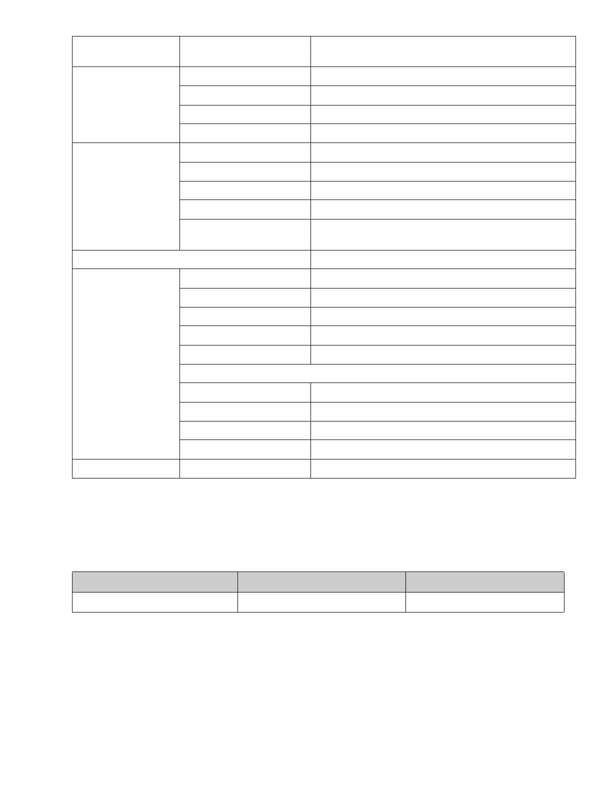
Table 2–1 Safety and Protective Devices
UNSAFE CONDITION SAFETY DEVICE DEVICE SETTING
Excessive current draw Fuse, Defrost Line Heater (FDLH) 5 amps

 Loading...


