3–1 T-319
SECTION 3
MICROPROCESSOR
3.1 TEMPERATURE CONTROL MICROPROCESSOR
The temperature control Micro-Link 3 microprocessor system consists of a keypad, display module, control module
(controller), and interconnecting wiring. This section addresses functions specific to the dual temperature platform.
For more detailed system information, refer to Section 3 of the Operations and Service manual for 69NT40-541-
300 to 349 series units.
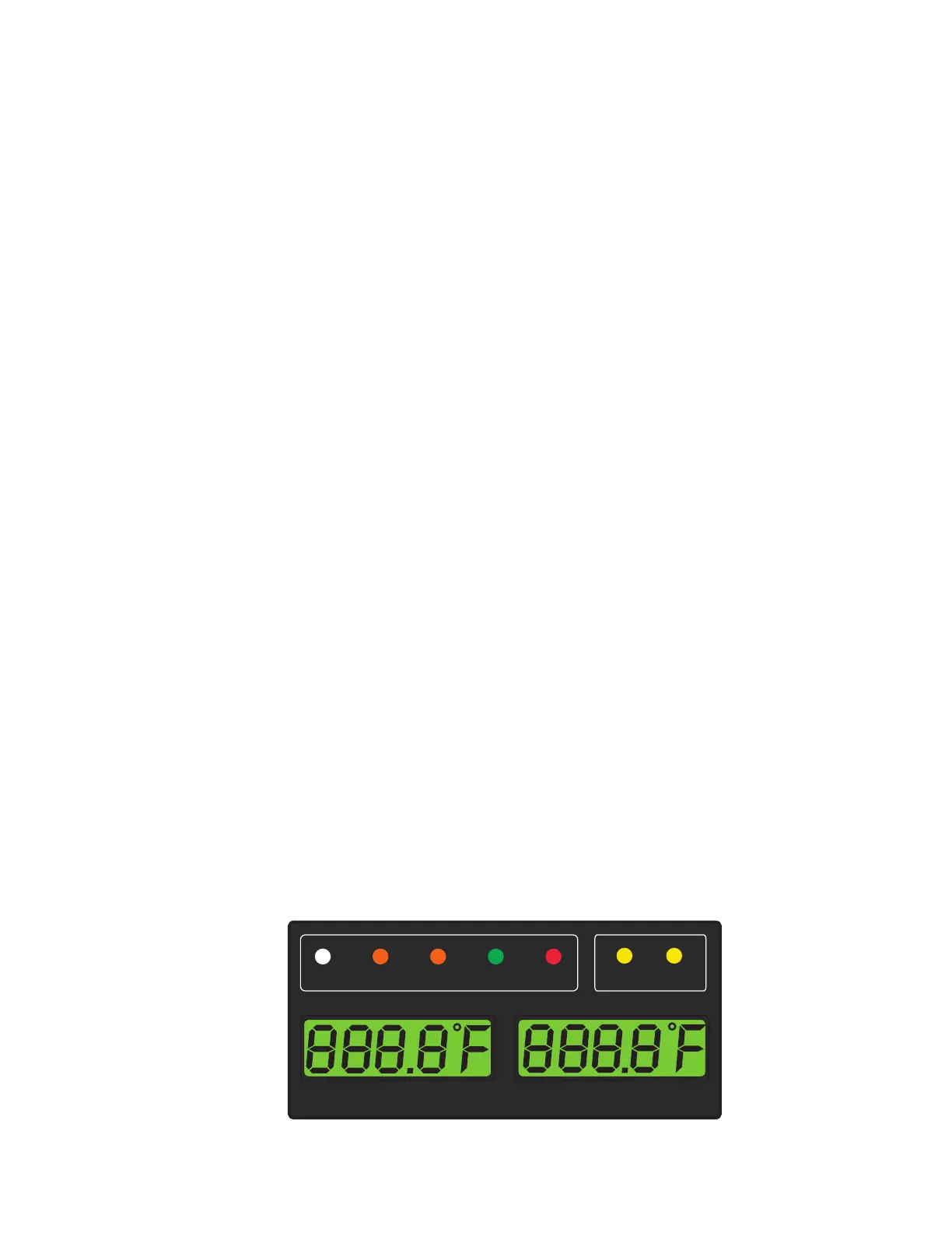
3.1.1 Display Module
The display module (Figure 3.1) consists of two 5-digit displays and seven indicator lights. The indicator lights
include:
1. Cool - White LED: Energized when the refrigerant compressor is energized.
2. Heat - Orange LED: Energized to indicate heater operation in the heat or defrost mode.
3. Defrost - Orange LED: Energized when the unit is in the defrost mode.
The in-range light is not illuminated until both compartments are in range.
4. In-Range - Green LED: Energized when the controlled temperature probe is within specified tolerance of set
point.
The host unit controlling probe in the perishable range will be the SUPPLY air probe and the con-
trolling probe in the frozen range will be the RETURN air probe. The Supply/Return light always indi-
cates the Host unit controlling probe.
5. Supply - Yellow LED: Energized when the supply air probe is used for control.When this LED is illuminated,
the temperature displayed in the AIRTEMPERATURE display is the reading at the supply air probe. This
LED will flash if dehumidification or humidification is enabled. The supply probe is used by the Remote com-
partment to control the temperature.
6. Return - Yellow LED: Energized when the return air probe is used for control.When this LED is illuminated,
the temperature displayed in the AIRTEMPERATURE display is the reading at the return air probe. This
LED will flash if dehumidification or humidification is enabled.
7. Alarm - Red LED: Energized when there is an active or an inactive shutdown alarm in the alarm queue.
The two displays include SETPOINT/Code and AIR TEMPERATURE/Data sections. The temperature display will
alternate between the Host and Remote evaporator compartment values. The Remote compartment values are
distinguishable by the “r” in the lower left hand corner of the left display.
Figure 3.1 Display Module
COOL HEAT DEFROST IN RANGE ALARM SUPPLY
RETURN
SETPOINT/Code AIR TEMPERATURE/Data

 Loading...


