1--6
T--304
04/08
1
1
2
2
3
4
4
6
8
5
6
7
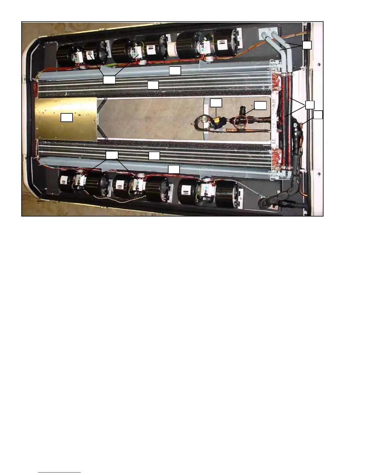
1. Evaporator Coil Assembly
2. Heater Coil
3. Expansion Valve
4. Evaporator Blower/Motor Assembly
5. Control Panel
6. Heater Line
7. Front Evaporator Port
8. Liquid Line Solenoid
Figure 1--5 Evaporator Section Components (AC350 Single Loop -- GEN II)
1.2.4 Drivers Evaporator (Optional)
Thedrivers evaporator assembly isnormally installedin
thevehicledashareaandinterfaceswiththerooftopunit
electrical cabeling and refrigerant piping.
The drivers evaporator assembly includes an
evaporator coil, thermal expansion valve, blower motor
assembly and a condensate drain connection. Refer to
the OEM technical literature for driver’s evaporator
information.
1.2.5 Compressor Assembly
a. Dual Loop Compressors A--6 & TM--21
The standard AC310 dual loop compressor assembly
includes the refrigerant compressor, clutch assembly,
in--line high & low pressure switches, suction
accumulator and in--line suction and discharge
servicing (charging) ports.
b. Single Loop Compressor TM--31
The TM--31 compressor assembly used only with the
AC310 Single Loop Unit includes the refrigerant
compressor, clutch assembly, suction & discharge
service valves, high pressure switch, low pressure
switch, suction accumulator and suction and discharge
servicing (charging) ports.
c. Single Loop Compressors 05G & 05K
The 05G (AC350) & 05K (AC310) compressor
assemblies used with the single loop units, includes the
clutch assembly, suction & discharge service valves,
high pressure switch, low pressure switch, suction and
discharge servicing (charging) ports and electric
solenoid unloaders.
Thecompressorraisesthepressureandtemperatureof
the refrigerant and forces it into the condenser coil
tubes. Theclutch assembly provides ameans of driving
the compressors by the vehicle engine. Suction and
discharge servicing (charging) ports mounted on the
compressor fittings enable connection of charging
hoses for servicing of the compressor , as well as other
parts of the refrigerant circuit. The high pressure switch
contacts open on a pressure rise to shut down the
system when abnormally high refrigerant pressures
occur.
The electric unloaders (05G & 05K) provide a means of
controlling compressor capacity, which enables control
of temperature inside the vehicle. The suction and
discharge service valves enable servicing of these
compressors.
 Loading...