T -304
5--5
04/08
5.10.2 Checking High Or Low Pressure Switches
WARNING
Do not use a nitrogen cylinder without a pres-
sure regulator
WARNING
Donotuseoxygeninorneararefrigerationsys-
tem as an explosion may occur.
a. Disconnect wiring and remove switch from system.
b. Connect an ohmmeter across switch terminals. If the
switch is good, the ohmmeter will indicate no resist-
ance, indicating that the contacts are closed.
c. Connect switch to a cylinder of dry nitrogen.
(SeeFigure 5--4).
6.
1.
2.
3.
4.
5.
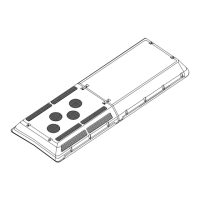
Figure 5--4 Checking High Pressure Switch
1. Cylinder Valve and Gauge
2. Pressure Regulator
3. Nitrogen Cylinder
4. Pressure Gauge (0 to 400 psig = 0 to 27.22 bar)
5. Bleed-Off Valve
6. 1/4 inch Connection
d. Set nitrogen pressure regulator higher than switch
cutout setting. (refer to paragraph 1.3.)
e. Open cylinder valve. Slowly open the regulator valve
to increase the pressure until it reaches cutout point.
The switch should open, which is indicated by an infi-
nite reading on an ohmmeter (no continuity).
f. Close cylinder valve and release pressure through
the bleed--off valve. As pressure drops to cut--in
point, the switch contacts should close, indicating no
resistance (continuity) on the ohmmeter.
g. Replace switch if it does not function as outlined
above.
5.11 FILTER-DRIER
2. 3. 4.
5.
6.
2.
3.
1.
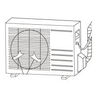
Figure 5--5 Filter--Drier Removal
1. Filter-Drier I nlet
Service Valve
2. Valve Service Port
3. Flare Nut
4. Filter-Drier
5. Liquid Line
Solenoid Valve
6. Filter-Drier Outlet
Service Valve
5.1 1.1 To Check Filter--Drier
Thefilter--drier(See Figure 5--5)must bechanged ifthe
system has been opened, (for any reason), or the filter
drier is partially restricted. Restriction can be identified
by either the outlet frosting or a temperature difference
between the inlet and outlet.
5.1 1.2 To Replace Filter--Drier Assembly
Filter Drier replacement can be accomplished by
performing either one of the two procedures
recommended.
1. System operating,lowsidepumpdown(refertosec-
tion 3.4.1).
2. System not operating (see below).
a. T urn the driver’s A/C switch to “OFF” position.
b. Frontseat the filter--drier service valves on bothsides
of the filter drier .
c. Place a new filter-drier near the unit for immediate
installation.
WARNING
The filter-drier may contain liquid refriger-
ant.Slowlyloosentheconnecting nutsand
avoid contact with exposed skin or eyes.
d. Using two open end wrenches, slowlycrack open the
connecting nuts on each side of the filter-drier as-
sembly . Remove the filter-drier assembly .
e. Remove seal caps from the new filter-drier. Apply a
light coat of mineral oil to the filter--drier connections.
f. Assemblethenewfilter-driertolinesensuringthatthe
arrowon thebody of thefilter-drier points in thedirec-
tion of the refrigerant flow (refrigerant flows from the
receiver to the evaporator). Finger tighten the con-
necting nuts.
g. Tighten filter-drier connecting nuts using two open
end wrenches.
h. Evacuate system (refer to section 5.7).
i. Backseat (fullyclose)bothservicevalveports andre-
place valve caps.
j. Check refrigerant charge (refer to section 5.8.1).
k. Remove Gauges.
 Loading...