T -304
5--7
04/08
Failure to open may be caused by the following:
1. Coil burned out or an open circuit to coil connections.
2. Improper voltage.
3. Defective plunger or deformed valve body assembly.
Failure to close may be caused by the following:
1. Defective plunger or deformed valve body assembly.
2. Foreign material in the valve.
5.13.1 Coil Replacement
a. It is not necessary to remove the refrigerant charge
from the system.
b. Disconnect system from bus battery.
c. Disconnect wire leads to coil.
d. Remove coil retaining clip and nameplate.
e. Lift failed coil from enclosing tube and replace.
f. Connect wire leads and test operation
5.13.2 Internal Part Replacement
a. Disconnect system from bus battery.
b. Recover and recycle system refrigerant.
c. Slowly loosen enclosing tube assembly to bleed any
remaining pressure from the valve. Disassemble
valve and replace defective parts.
d. Assemble valve and leak check.
e. Evacuate and recharge system.
5.13.3 Replace Entire Valve
a. Recover and recycle system refrigerant.
b. Remove valve assembly from bracket.
c. Disconnect wire leads to coil.
d. Disassemblenew valve, to protectinternal parts,and
solder to lines.
e. Assemble and leak check valve.
f. Evacuate and recharge.system.
g. Connect wire leads and test operation.
1.
2.
3.
4.
5.
6.
7.
8.
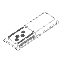
Figure 5--7 Liquid Line Solenoid Valve
1. Snap Cap
2. Coil Assembly
3. Enclosing Tube
Assembly
4. Plun
er Assembl
5. Gasket
6. Piston Assembly
7. Body
8. Bracket Adapter
5.14 SER VICE V ALVES
The filter/drier (High Side) service valves (Figure 5--8)
areprovidedwith adouble seat and agauge port, which
allows servicing of the filter drier assembly.
T urning the valve stem counterclockwise (all the way
out) will backseat the valve to open the line to the
system and close off the gauge port. In normal
operation, the valve is backseated to allow full flow
through the valve. The valve should always be
backseated before removing the gauge port cap.
T urning the valve stem clockwise (all the way forward)
will frontseat the valve to isolate the system and open
the gauge port.
SERVICE
PORT
VALVE CAP
VALVE
STEM
TO DISCHARG LINE
Service Valve
Frontseated
(clockwise)
Service Valve
Backseated
(counterclockwise)
Port To
Compressor
Figure 5--8 Service Valve R134a (High Side)
 Loading...