T -304
5--2
04/08
CAUTION
The AC310 & AC350 Rooftop Systems have
R134a service port couplings installed on
the compressor and 1/4 inch flare (Acme)
fittings installed on the unit piping.
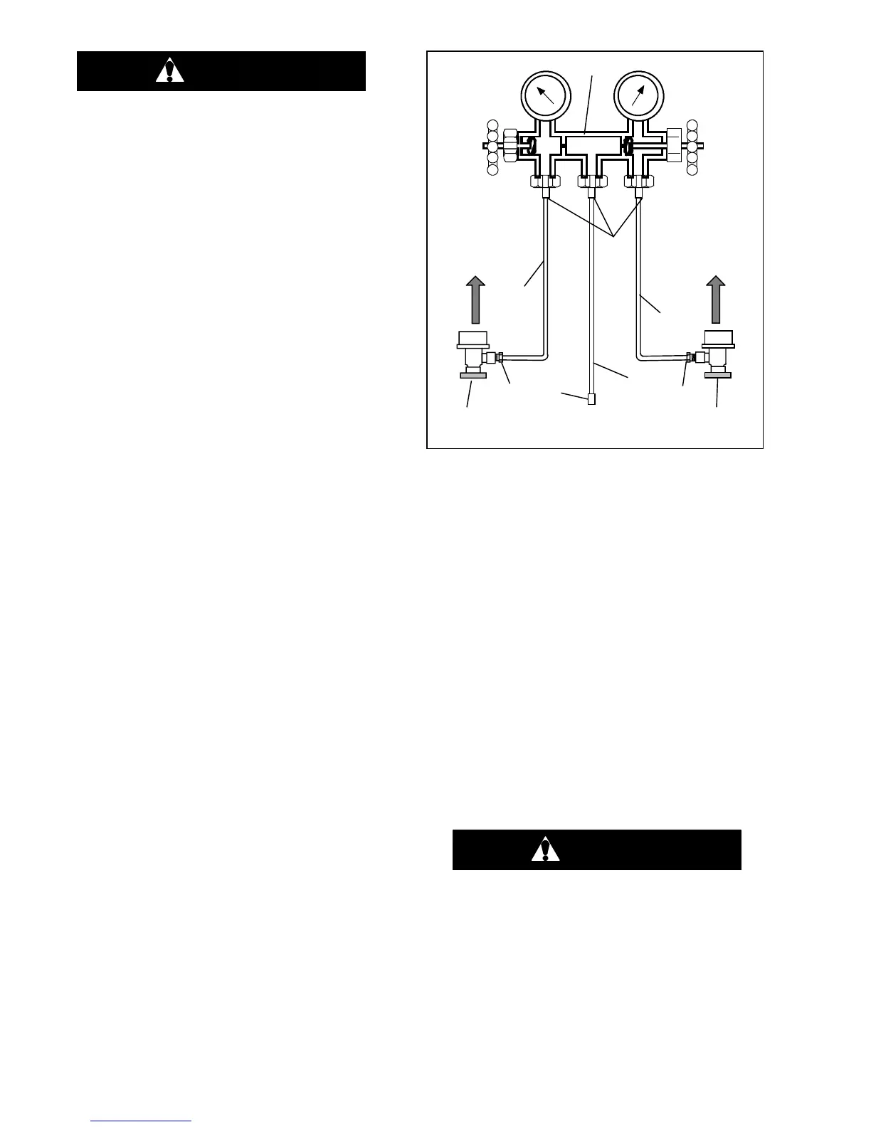
5.4.1 Installing R--134a Manifold Gauge/Hose SET
An R--134a manifold gauge/hose set with self--sealing
hoses is pictured in Figure 5--1. The manifold
gauge/hose set is available from Carrier Transicold.
(Carrier T ransicold P/N 07--00294--00, which includes
items1through6,Figure 5--1).Toperformserviceusing
the manifold gauge/hose set, do the following:
a. Preparing Manifold Gauge/Hose Set for use.
1. If the manifold gauge/hose set is new or was ex-
posedtotheatmosphere itwill needtobeevacuated
to remove contaminants and air as follows:
2. Back--seat (turncounterclockwise) bothfieldservice
couplers (see Figure 5--1) and mid--seat both hand
valves.
3. Connect the yellow hose to a vacuum pump and an
R--134a cylinder.
4. Evacuate to 10 inches of vacuum and then charge
with R134a to slightly positive pressure of 1.0 psig.
5. Front--seatbothmanifoldgaugesethandvalvesand
disconnect from cylinder. The gauge set is now
ready for use.
OPENED
(Backseated )
HAND VALVE
CLOSED
(Frontseated)
HAND VALVE
SUCTION
PRESSURE
GAUGE
DISCHARGE
PRESSURE
GAUGE
To Low Side
Access Valve
To High Side
Access Valve
Red Knob
Blue Knob
4.
3.
YELLOW
2.
4.
5.
6.
3.
RED
3.
BLUE
2.
1.
To Refrigerant Tank
or V acuum Pump
Figure 5--1 Manifold Gauge Set (R--134a)
1. Manifold Gauge Set
2..Hose Fitting (0.5-16 Acme)
3..Refrigeration and/or Evacuation Hose
. (SAE J2196/R-134a)
4..Hose Fitting w/O-ring (M14 x 1.5)
5..High Side Field Service Coupling
6..Low Side Field Service Coupling
b. Connecting the Manifold Gauge Gauge/Hose Set.
To connect the manifold gauge/hose set for reading
pressures, do the following:
1. Connect the field service couplers (see Figure 5--1)
to the high and low in--line service ports.
2. T urn the field service coupling knobs clockwise,
which will open the system to the gauge set.
3. Read the system pressures.
c. Removing the Manifold Gauge Set.
1. While the compressor is still ON, mid--seat both
hand valves on the manifoldgauge setand allowthe
pressureinthemanifold gaugeset tobedrawndown
tolow sidepressure. Thisreturns anyliquidthat may
be in t he high side hose to the system.
CAUTION
To prevent trapping liquid refrigerant in the
manifoldgaugesetbesuresetisbroughtto
suction pressure before disconnecting.
2. Back--seatbothfieldservicecouplers andfront--seat
bothmanifold sethandvalves.Removethecouplers
from the in--line access valves.
3. Install both in--line access valve caps.
 Loading...