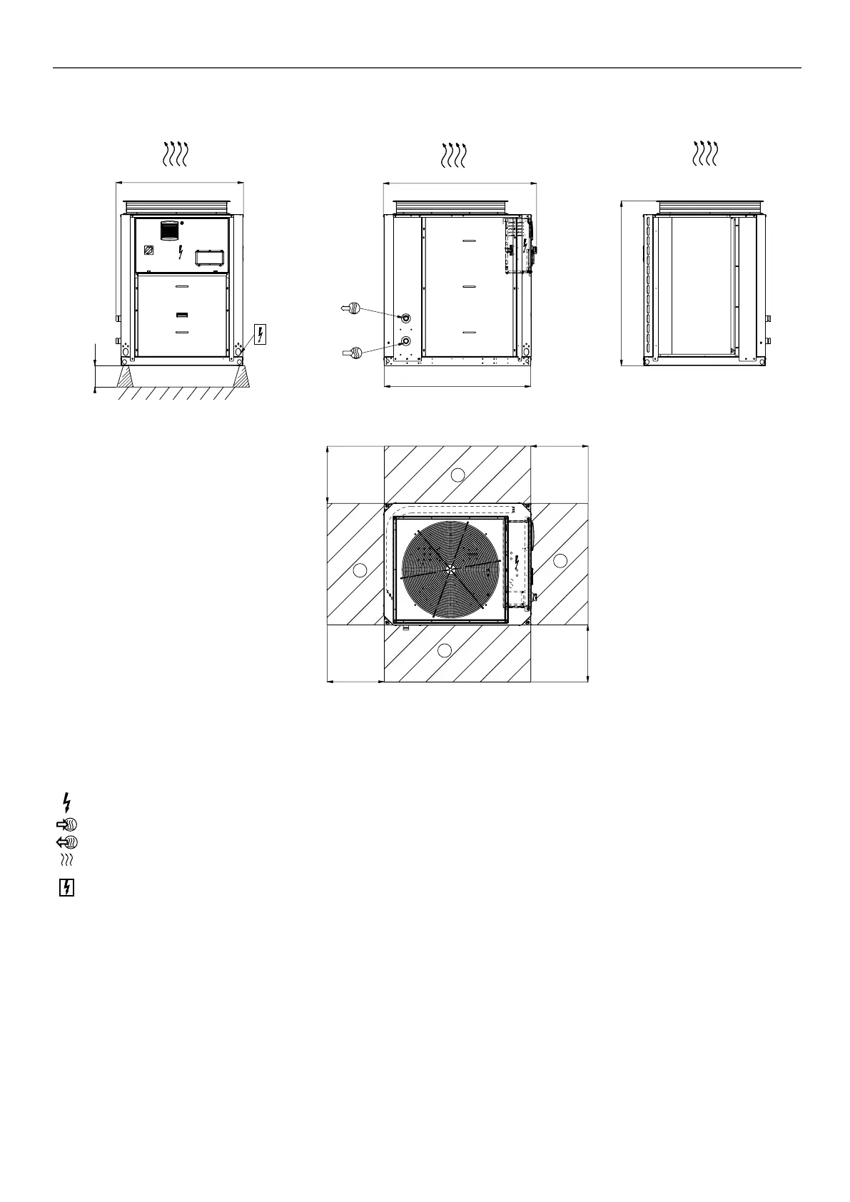
3.4 - 61AF 035 option 11, units with and without hydraulic module
1110
300
1280
1327
1371
1000
1000
1000
1000
1
1
2
2
Legend :
All dimensions are given in mm mm.
NOTES: :
A Non-certied drawings.
Refer to the certied dimensional drawings supplied with
the unit or available on request, when designing an
installation. For the location of xing points, weight
distribution and coordinates of the centre of gravity refer
to the certied dimensional drawings.
B In multiple-unit installations (maximum four units), the
side clearance between the units should be increased
from 1000 to 2000 mm.
C The height of the solid surface must not exceed 2 m.
B
Required clearances for air ow
C
Recommended clearances for maintenance
Control box
Water inlet
Water outlet
Air outlet, do not obstruct
Air outlet, do not obstruct
3 - DIMENSIONS, CLEARANCES
 Loading...


