MODULE #1 – DIGITAL DISPLAY
Blood Bank & Incubator Models
Vendor – Analogic
Effective Through June, 2002
GENERAL
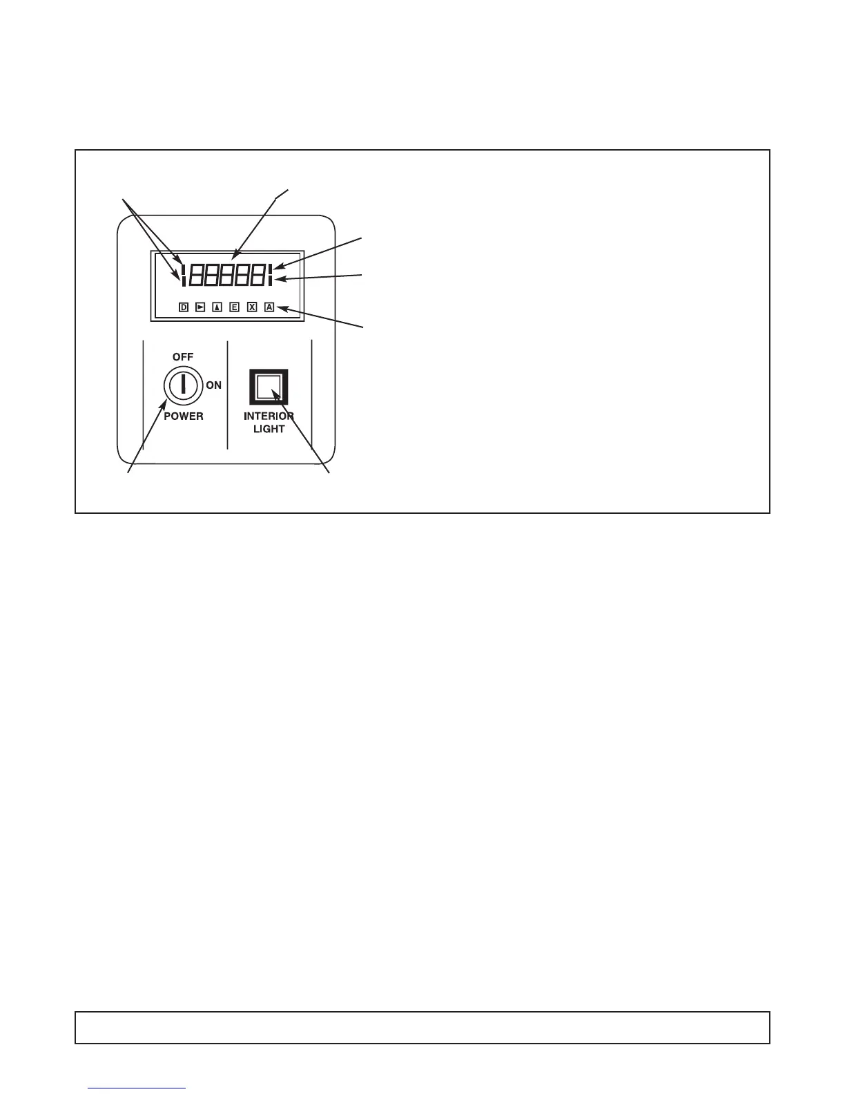
This module contains the ON/OFF power switch, inte-
rior cabinet light switch and digital meter displaying
cavity temperature.
1. Cabinet power is controlled by a keyed ON/OFF
switch. The key is removable in both positions. In
the OFF position the battery charger and power
failure relay in the optional Alarm System Module
are still energized. CAUTION - Risk of Electrical
Shock. Disconnect Power Before Servicing.
2. Interior cabinet light is controlled by a push button. In
the recessed position, cabinet light is on and the
switch will glow (on glass door cabinet and incubator
only).
3. The digital process meter monitors cavity conditions.
Cabinet temperature is displayed on a green vacuum
fluorescent display in degrees centigrade (°C). Four
red status indicators que the attendant of display
mode and temperature alarm conditions. The maxi-
mum (peak) temperature and minimum (valley) tem-
perature are saved for instant recall at a later time.
The unit may be provided with alarm relay contacts
for audio, visual and remote signaling from the
optional Alarm System Module. Also a 420 mA
process signal may be incorporated within the unit to
drive an optional circular chart recorder.
SETTING & REVIEWING PARAMETERS
1. In normal mode of operation the instrument displays
the current temperature reading. By pressing the ‘D’
key, other values and operating parameters may be
sequentially reviewed. While the ‘D’ key is held down
a code indicating the parameter is displayed; when
the key is released, the parameter value is shown
(See Table 1 for parameters).When these values are
displayed, the two left side red indicator bars are lit,
indicating a non-standard display (See Figure 1).
2. When the desired parameter value is displayed,
press k key to enter numeric entry mode. One digit
will blink (for changing values only).
3. Press the m key to adjust this digit to the desired
value, then press k to select the next digit.
4. When the right most digit is blinking and correct,
press the ‘E’ key to store the value and return to nor-
mal meter operation.
5. If a mistake is made at any point before the ‘E’ key is
pressed, press the ‘X’ key to cancel the operation and
return to the default display.
6. The peak or valley values may be reset to the current
display by pressing the ‘E’ key when the value is dis-
played.
BUTTON FUNCTIONS
DDISPLAY Display next parameters
in order
k RIGHT Make first Digit active.
Then step right one digit.
m UP Increment active digit by one.
E ENTER Enter the displayed value in
parameter memory or reset
peak or valley measurement.
X EXIT Cancel current operation
and display interior cabinet
temperature.
ANOT USED
9-Segment Display
Lit When Not
Showing Cavity
Temperature in °C
Low Temp.
Alarm Indicator
High Temp.
Alarm Indicator
Buttons
Located
Behind Hinged
Access Cover
Cabinet Interior Light Switch
(Glass Door Cabinets & Incubators)
Keyed ON/OFF
Power Switch
82 MODULE #1
FIGURE 1