ALARM SYSTEMS COMPONENTS
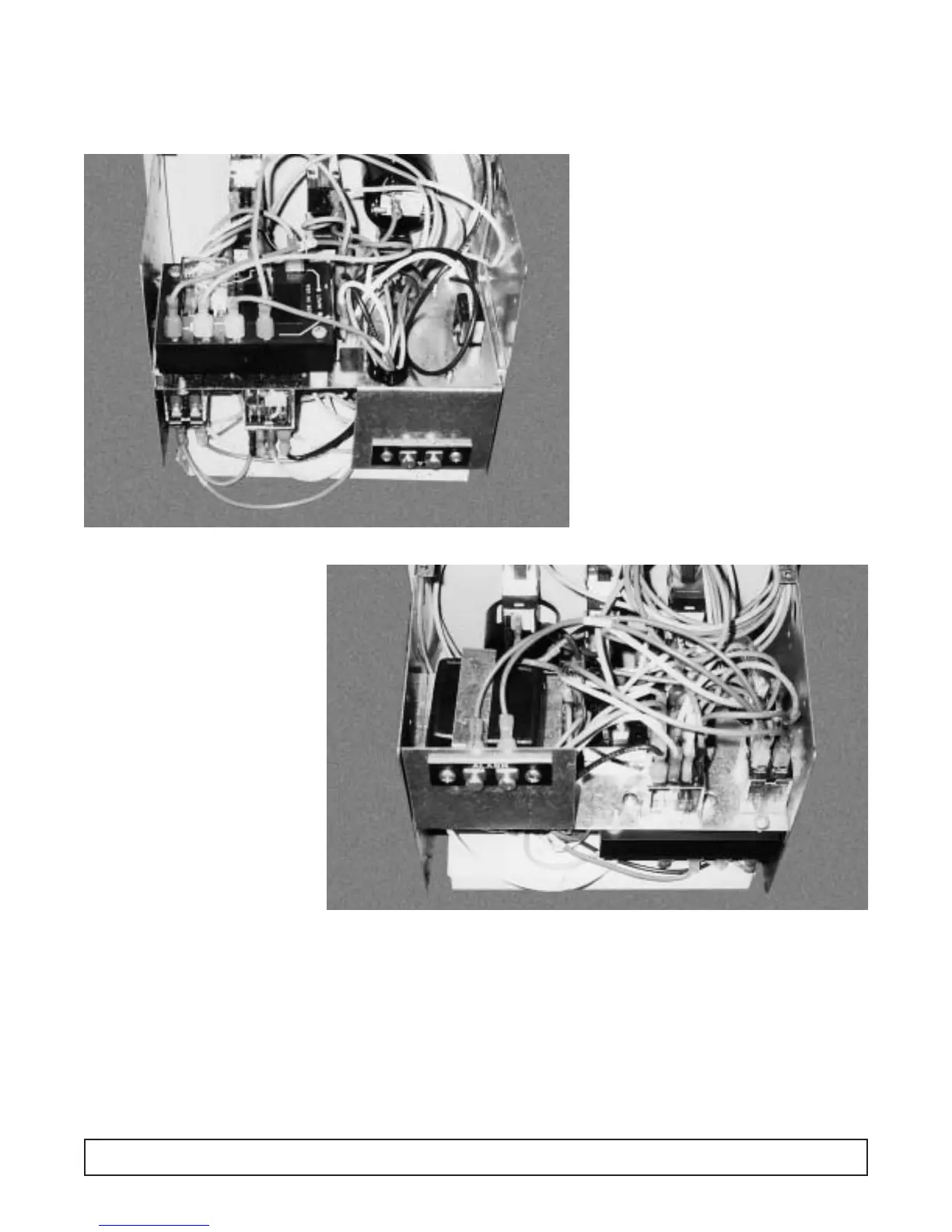
Rear Views of an Alarm Module
1 Battery Charger
26 Volt Relay
3 120 Volt Relay
4Silence Indicator Light
5Time Delay Relay
6Test Switch
7High Temp. Indicator
8Low Temp Indicator
9Power Failure
10 Remote Alarm Contacts
11
11
22
22
33
33
77
77
99
99
88
88
44
44
66
66
55
55
Emergency
Procedure Planning:
Post adjacent to, or on the cabinet
door, instructions to follow in the
event of an alarm condition:
1. Persons to be notified and the
telephone numbers of each;
2 The location of other refrigera-
tor/freezers that might have the
space for emergency storage;
3. The telephone numbers to
call for electrical refrigeration
system repair.
11
11
00
00
ALARM SYSTEMS COMPONENTS 87