2
CONTENTS (cont)
Page
Cooler and Condenser (30HXC)
Pump Control
. . . . . . . . . . . . . . . . . . . . . . . . . . . . . . . . . . . 14
• COOLER PUMP CONTROL
• CONDENSER PUMP CONTROL
Cooler Heater Control
. . . . . . . . . . . . . . . . . . . . . . . . . . . 15
Oil Heater Control
. . . . . . . . . . . . . . . . . . . . . . . . . . . . . . . 15
Keypad and Display Module
(Also Called HSIO-II)
. . . . . . . . . . . . . . . . . . . . . . . . . . 15
• ACCESSING FUNCTIONS
AND SUBFUNCTIONS . . . . . . . . . . . . . . . . . . . . . . . . 15
• AUTOMATIC DEFAULT DISPLAY . . . . . . . . . . . . . . 15
• STATUS FUNCTION . . . . . . . . . . . . . . . . . . . . . . . . . . 19
• TEST FUNCTION . . . . . . . . . . . . . . . . . . . . . . . . . . . . 27
• HISTORY FUNCTION. . . . . . . . . . . . . . . . . . . . . . . . . 27
• SET POINT FUNCTION . . . . . . . . . . . . . . . . . . . . . . . 27
• SERVICE FUNCTION . . . . . . . . . . . . . . . . . . . . . . . . . 32
• SCHEDULE FUNCTION. . . . . . . . . . . . . . . . . . . . . . . 39
Temperature Reset
. . . . . . . . . . . . . . . . . . . . . . . . . . . . . . 41
• EXTERNAL TEMPERATURE RESET
• EXTERNALLY POWERED RESET
• RETURN FLUID TEMPERATURE RESET
Demand Limit
. . . . . . . . . . . . . . . . . . . . . . . . . . . . . . . . . . . 41
• DEMAND LIMIT (Switch Controlled, 30GX Only)
• EXTERNALLY POWERED DEMAND LIMIT
• DEMAND LIMIT (CCN Loadshed Controlled)
TROUBLESHOOTING
. . . . . . . . . . . . . . . . . . . . . . . . . 45-54
Checking Display Codes
. . . . . . . . . . . . . . . . . . . . . . . . 45
Unit Shutoff
. . . . . . . . . . . . . . . . . . . . . . . . . . . . . . . . . . . . . 45
Complete Unit Stoppage
. . . . . . . . . . . . . . . . . . . . . . . . 45
Single Circuit Stoppage
. . . . . . . . . . . . . . . . . . . . . . . . . 45
Restart Procedure
. . . . . . . . . . . . . . . . . . . . . . . . . . . . . . . 45
• POWER FAILURE EXTERNAL TO THE UNIT
Alarms and Alerts
. . . . . . . . . . . . . . . . . . . . . . . . . . . . . . . 45
Compressor Alarm/Alert Circuit
. . . . . . . . . . . . . . . . . 46
EXD Troubleshooting Procedure
. . . . . . . . . . . . . . . . 52
• INSPECTING/OPENING ELECTRONIC
EXPANSION VALVES
• INSPECTING/OPENING ECONOMIZERS
SERVICE
. . . . . . . . . . . . . . . . . . . . . . . . . . . . . . . . . . . . . 54-68
Servicing Coolers and Condensers
. . . . . . . . . . . . . . 54
• TUBE PLUGGING
• RETUBING
• TIGHTENING COOLER/CONDENSER
HEAD BOLTS
Inspecting/Cleaning Heat Exchangers
. . . . . . . . . . . 55
•COOLERS
• CONDENSERS (30HX Only)
Water Treatment
. . . . . . . . . . . . . . . . . . . . . . . . . . . . . . . . . 55
Condenser Coils (30GX Only)
. . . . . . . . . . . . . . . . . . . 55
• COIL CLEANING
Condenser Fans (30GX Only)
. . . . . . . . . . . . . . . . . . . . 56
Refrigerant Charging/Adding Charge
. . . . . . . . . . . . 56
Oil Charging/Low Oil Recharging
. . . . . . . . . . . . . . . . 57
Oil Filter Maintenance
. . . . . . . . . . . . . . . . . . . . . . . . . . . 58
• REPLACING THE EXTERNAL OIL FILTER
• REPLACING THE INTERNAL OIL FILTER
Compressor Changeout Sequence
. . . . . . . . . . . . . . 58
• BURNOUT CLEAN-UP PROCEDURE
Moisture-Liquid Indicator
. . . . . . . . . . . . . . . . . . . . . . . . 60
Filter Drier
. . . . . . . . . . . . . . . . . . . . . . . . . . . . . . . . . . . . . . . 60
Liquid Line Service Valve
. . . . . . . . . . . . . . . . . . . . . . . . 60
Thermistors
. . . . . . . . . . . . . . . . . . . . . . . . . . . . . . . . . . . . . 61
•LOCATION
• THERMISTOR REPLACEMENT
Pressure Transducers
. . . . . . . . . . . . . . . . . . . . . . . . . . . 61
• PRESSURE TRANSDUCER CALIBRATION
• TROUBLESHOOTING
Safety Devices
. . . . . . . . . . . . . . . . . . . . . . . . . . . . . . . . . . 64
• COMPRESSOR PROTECTION
• OIL SEPARATOR HEATERS (30GX)
• COOLER PROTECTION
Relief Devices
. . . . . . . . . . . . . . . . . . . . . . . . . . . . . . . . . . . 64
• PRESSURE RELIEF VALVES
Control Modules
. . . . . . . . . . . . . . . . . . . . . . . . . . . . . . . . . 65
• PROCESSOR MODULE (PSIO-1), COMPRESSOR
PROTECTION MODULE (CPM), HIGH VOLTAGE
RELAY MODULE (DSIO-HV), AND EXV DRIVER
MODULE (DSIO-EXV), 12/6 MODULE (PSIO-2)
• RED LED
• GREEN LED
• CONTROL MODULE BATTERY REPLACEMENT
Carrier Comfort Network (CCN) Interface
. . . . . . . . 66
• PROCESSOR MODULE (PSIO-1)
• HIGH VOLTAGE RELAY MODULE (DSIO-HV)
Replacing Defective Processor Module
. . . . . . . . . . 68
Winter Shutdown Preparation
. . . . . . . . . . . . . . . . . . . 68
PRE-START-UP PROCEDURE
. . . . . . . . . . . . . . . . . . . . 69
System Check
. . . . . . . . . . . . . . . . . . . . . . . . . . . . . . . . . . . 69
START-UP AND OPERATION
. . . . . . . . . . . . . . . . . . . . . 69
Actual Start-up
. . . . . . . . . . . . . . . . . . . . . . . . . . . . . . . . . . 69
Operating Sequence
. . . . . . . . . . . . . . . . . . . . . . . . . . . . . 69
FIELD WIRING
. . . . . . . . . . . . . . . . . . . . . . . . . . . . . . . . 70-75
APPENDIX A
(Compressor Must Trip Amps)
. . . . . . . . . . . . . 76-80
APPENDIX B
(Capacity Loading Sequence)
. . . . . . . . . . . . . . 81-85
APPENDIX C (Available Accessories)
. . . . . . . . . 86,87
APPENDIX D (Building Interface)
. . . . . . . . . . . . . 88-92
APPENDIX E (Cooler and
Condenser Pressure Drop)
. . . . . . . . . . . . . . . . . 93-96
APPENDIX F
(Typical System Components)
. . . . . . . . . . . . . 97,98
INDEX
. . . . . . . . . . . . . . . . . . . . . . . . . . . . . . . . . . . . . . . . . . . 99
START-UP CHECKLIST
. . . . . . . . . . . . . . . . .CL-1 to CL-8
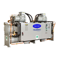
GENERAL
This publication contains Start-Up, Service, Controls, Oper-
ation and Troubleshooting data for the 30GX080-350 and
30HXA,C076-271 screw chillers.
Circuits are identified as circuits A and B, and compressors
are identified as A1 or A2 in circuit A, and B1 or B2 in
circuit B.
The 30GX,HX Series chillers feature microprocessor-based
electronic controls and electronic expansion devices (EXD) in
each refrigeration circuit.
The control system cycles compressor loaders and/or com-
pressors to maintain the selected leaving fluid temperature set
point. The system automatically positions the EXD to maintain
the specified refrigerant level in the cooler. The system also has
capabilities to control a condenser water valve to maintain suit-
able leaving-water temperature for the 30HXC unit. Safeties
are continuously monitored to prevent the unit from operating
under unsafe conditions. A scheduling function can be pro-
grammed by the user to control the unit’s occupied and unoc-
cupied schedules. The control also operates a test function and
a manual control function that allows the operator to check out-
put signals and ensure components are operable.
The control system consists of a processor module
(PSIO-1), an EXD driver module (DSIO-EXV), a high voltage
relay module on 30GX units (DSIO-HV), 2 six-pack relay
boards, a keypad and display module (also called HSIO-II),
2 electronic expansion devices (EXDs), 1 compressor protec-
tion module (CPM) per pair of compressors, a PSIO-2 module,
IMPORTANT: The 30GX,HX units use refrigerant
R-134a. Compressor oil used with R-134a is Polyolester
oil.
 Loading...


