5
The CPM has the following 4 output relays and 4 inputs:
OUTPUTS:
• compressor contactor
• compressor oil solenoid
• compressor motor cooling solenoid
• Wye-Delta transition relay
INPUTS:
• motor temperature
• three-phase current
• high-pressure switch
A diagram of the CPM board is (HN67LM101) shown in
Fig. 1. One CPM board is installed on 30GX080-176 and
30HXA,C076-186 units, and 2 CPM boards are installed on
30GX205-350 and 30HXA,C206-271 units. The address for
each CPM board is set using DIP (dual in-line package)
switches 3 and 4. For CPM1 (compressors A1 and B1), both
DIP switches should be set to 0. For CPM2 (compressor A2,
for 30GX205-265 and 30HXA,C206-271 units only and com-
pressors A2 and B2 for 30GX281-350 only), both switches
should be set to 1. See Table 3 for CPM board connections.
The CPM has a reset button located between the DIP switch
and the J10 connector. Pressing the reset button on the CPM
will clear any current CPM alarms, but will not turn off any
outputs from the CPM. Pressing the reset button on the CPM
will NOT cause the board to go through initialization. Initial-
ization period only occurs during power-up and lasts for ap-
proximately 2 minutes. Each compressor’s MTA (must trip
amps) setting is communicated to the PSIO-1 during the initial-
ization period. Switches 1 and 2 should be set to 0. See Table 4
for DIP switch settings.
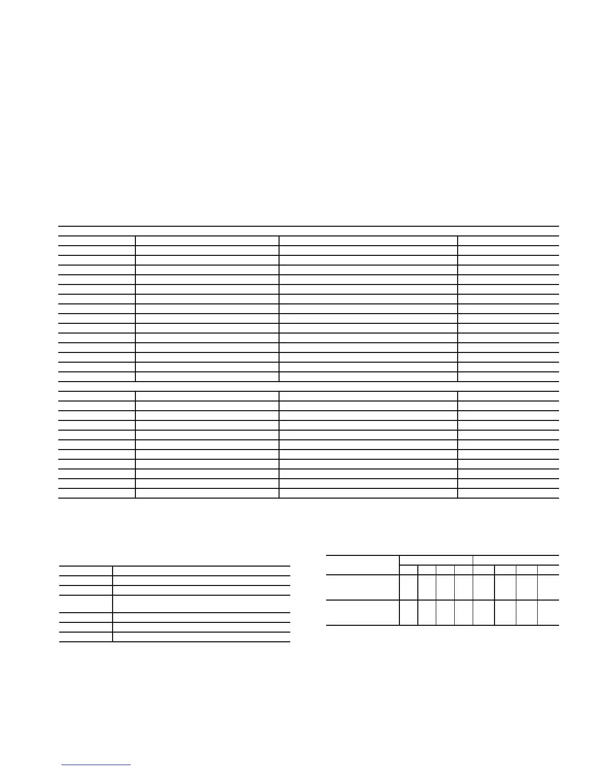
Table 2 — Thermistor and Transducer Locations
*30HX206-271 and 30GX205-265 only.
†Sensors are available as accessories for field installation.
Table 3 — Compressor Protection Module
(CPM) Plug Connections
NOTE: Plugs J2-J5 are for compressors A1 (CPM1) or A2 (CPM2).
Plugs J6-J9 are for compressor B1 (CPM1) or B2 (CPM2).
Table 4 — CPM Address DIP Switch Settings:
THERMISTORS
Sensor Description Location Connection Terminals
T1
Cooler Leaving Fluid Temp Cooler Head Leaving Fluid Side PSIO-2, J7 pins 2,3
T2
Cooler Entering Fluid Temp Cooler Head Entering Fluid Side PSIO-2, J7 pins 5,6
Motor Temp A1
Motor Temperature A1 Compressor A1 Junction Box CPM1, plug J5
Motor Temp A2*
Motor Temperature A2 Compressor A2 Junction Box CPM2, plug J5
Motor Temp B1
Motor Temperature B1 Compressor B1 Junction Box CPM1, plug J9
Motor Temp B2†
Motor Temperature B2 Compressor B2 Junction Box CPM1, plug J9
T5
Discharge Gas Temp A Top of Oil Separator Circuit A PSIO-2, J7 pins 8,9
T6
Discharge Gas Temp B Top of Oil Separator Circuit B PSIO-2, J7 pins 11,12
LL-A (T3)
Liquid Level Circuit A Top of Cooler Circuit A PSIO-1, J7 pins 5,6
LL-B (T4)
Liquid Level Circuit B Top of Cooler Circuit B PSIO-1, J7 pins 8,9
T7 (optional)**
Outdoor Air Thermistor Outside Air Stream PSIO-2, J7 pins 20,21
STP (optional)**
Space Temperature Conditioned Space PSIO-2, J7 pins 23,24
T8 (optional)**
Condenser Entering Water Thermistor Condenser Entering Fluid Line PSIO-2, J7 pins 14,15
T9 (optional)**
Condenser Leaving Water Thermistor Condenser Leaving Fluid Line PSIO-2, J7 pins 17,18
PRESSURE TRANSDUCERS
Sensor Description Location Connection Terminals
DPT-A
Discharge Pressure Circuit A Top of Condenser Separator Circuit A PSIO-1, J7 pin 22
SPT-A
Suction Pressure Circuit A Top of Cooler Circuit A PSIO-1, J7 pin 19
EPT-A
Economizer Pressure Circuit A Economizer Line Entering Comp A PSIO-1, J7 pin 10
OPT-A1
Oil Pressure Compressor A1 Compressor A1 Oil Connection PSIO-1, J7 pin 25
OPT-A2*
Oil Pressure Compressor A2 Compressor A2 Oil Connection PSIO-1, J7 pin 1
DPT-B
Discharge Pressure Circuit B Top of Oil Separator Circuit B PSIO-1, J7 pin 16
SPT-B
Suction Pressure Circuit B Top of Cooler Circuit B PSIO-1, J7 pin 31
EPT-B
Economizer Pressure Circuit B Economizer Line Entering Comp B PSIO-1, J7 pin 13
OPT-B1
Oil Pressure Compressor B1 Compressor B1 Oil Connection PSIO-1, J7 pin 28
OPT-B2†
Oil Pressure Compressor B2 Compressor B1 Oil Connection PSIO-1, J7 pin 16
CPM PLUG DESCRIPTION
J1
24-vac Power Input
J2, J6
Compressor Contactor(s)
J3, J7
High Pressure Switch, Oil and Motor Cooling
Solenoids
J4, J8
Current Sensor Input
J5, J9
Compressor Motor Temperature Input
J10, J11
Communication Connections
UNIT
CPM1 CPM2
1234 1 2 3 4
30GX080-176
30HXA076-186
30HXC076-186
0000————
30GX205-350
30HXA206-271
30HXC206-271
0000 0 0 1 1

 Loading...