7
WIRED CONTROLLER INSTALLATION PRECAUTION
1. This manual provides the wired controller installation method. Refer to the wiring diagram in
this installation manual to wire the wired controller with the indoor unit.
2. The wired controller works in a low voltage loop circuit. Do not connect directly to 208/230V
and 460V. Do not wire this kind of wire into a loop. Wiring clearance between the configured
tubes should range 11.81−19.69 inches (30−50 cm) or above.
3. The shielded wire of the wired controller must be properly grounded.
NOTE: Upon completion of the wired controller connection, do not use a tramegger to test the
insulation.
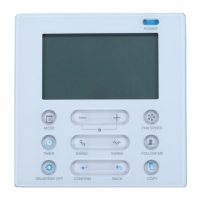
CONTROLLER DIMENSIONS
123mm
(4.8”)
120mm
(4.7”)
18.5mm
(0.7”)
83.5mm
(3.3”)
46mm
(1.8”)
62mm
(2.4”)
Fig. 1 - Wired Remote Controller Dimensions
red
black
yellow
brown
red
black
yellow
brown
Insert of the
mainboard CN40
Wire controller
Indoor unit mainboard
4-Core Shield Cable, the length
is decided by installation
-----------------------------------
-----------------------------------
-----------------------------------
-----------------------------------
Fig. 2 - Wiring Connection Diagram
 Loading...